Hi,
1. Since I need to use PWM DMA to transfer 320 bytes of data to the PWM for sequential playback.
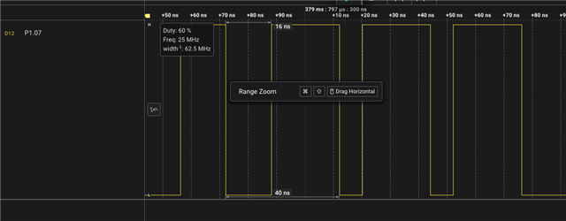
2. I wrote the following test example to test the nrfx pwm driver, but I haven't captured the waveform of the PWM IO port. Please assist me in troubleshooting the issue.
// /*
//  * Copyright (c) 2012-2014 Wind River Systems, Inc.
//  *
//  * SPDX-License-Identifier: Apache-2.0
//  */

// #include <stdio.h>
// #include <zephyr/sys/printk.h>
// #include <nrfx_pwm.h>
// #include "user_debug.h"
// // // 翻转 GPIOx,指示一帧发送完成
// // USER_DEBUG(USER_GPIO1, TOGGLE);
// // USER_DEBUG(USER_GPIO2, TOGGLE);
// // USER_DEBUG(USER_GPIO3, TOGGLE);
// // USER_DEBUG(USER_GPIO4, TOGGLE);

// /* 定义 PWM 实例索引(使用 PWM20) */
// #define PWM_INST_IDX 20

// /* 引脚映射辅助宏(与原始示例兼容) */
// #define USER_GPIO_PIN_MAP(port, pin)   (((pin) & 0x1F) | ((port) << 5))
// #define I2S_PLUS_PIN    USER_GPIO_PIN_MAP(1, 6)
// #define I2S_MINUS_PIN   USER_GPIO_PIN_MAP(1, 7)

// /* PWM 实例(使用索引获取) */
// static nrfx_pwm_t m_pwm = NRFX_PWM_INSTANCE(NRF_PWM_INST_GET(PWM_INST_IDX));

// /* 定义 IRQ 处理函数(nrfx 4.0 新方式) */
// NRFX_INSTANCE_IRQ_HANDLER_DEFINE(pwm, PWM_INST_IDX, &m_pwm);

// /* PWM 序列数据(individual 模式,每个通道独立值) */
// static nrf_pwm_values_individual_t m_seq_values;
// static nrf_pwm_sequence_t const m_seq = {
//     .values.p_individual = &m_seq_values,
//     .length              = 1,   // 只有一个序列条目(包含四个通道值)
//     .repeats             = 0,
//     .end_delay           = 0,
// };

// /**
//  * @brief PWM 事件处理函数(简单打印,不停止播放)
//  *
//  * @param[in] event_type PWM 事件类型
//  * @param[in] p_context  上下文指针(未使用)
//  */
// static void pwm_handler(nrfx_pwm_event_type_t event_type, void *p_context)
// {
//     (void)p_context;
//     if (event_type == NRFX_PWM_EVENT_FINISHED) {
//         printk("PWM playback loop finished (continuing due to LOOP flag)\n");
//     }
// }

// /**
//  * @brief 初始化并启动 PWM 输出
//  */
// void pwm_test(void)
// {
//     /* 配置 PWM 输出引脚、时钟、计数模式等 */
//     nrfx_pwm_config_t config = {
//         .output_pins = {
//             I2S_PLUS_PIN,
//             I2S_MINUS_PIN,
//             NRF_PWM_PIN_NOT_CONNECTED,
//             NRF_PWM_PIN_NOT_CONNECTED,
//         },
//         .pin_inverted  = {false, false, false, false},
//         .irq_priority  = NRFX_PWM_DEFAULT_CONFIG_IRQ_PRIORITY,
//         .base_clock    = NRF_PWM_CLK_1MHz,
//         .count_mode    = NRF_PWM_MODE_UP,
//         .top_value     = 1000,       // PWM 周期 = 1MHz / 1000 = 1kHz
//         .load_mode     = NRF_PWM_LOAD_INDIVIDUAL,
//         .step_mode     = NRF_PWM_STEP_AUTO,
//         .skip_gpio_cfg = false,
//         .skip_psel_cfg = false,
//     };

//     nrfx_err_t err = nrfx_pwm_init(&m_pwm, &config, pwm_handler, NULL);
//     if (err != NRFX_SUCCESS) {
//         printk("nrfx_pwm_init failed: %d\n", err);
//         return;
//     }

//     /* 设置各通道的占空比(基于 top_value = 1000) */
//     m_seq_values.channel_0 = 500;   // 50% 占空比
//     m_seq_values.channel_1 = 250;   // 25% 占空比
//     m_seq_values.channel_2 = 0;
//     m_seq_values.channel_3 = 0;

//     /* 开始播放,无限循环(NRFX_PWM_FLAG_LOOP) */
//     nrfx_pwm_simple_playback(&m_pwm, &m_seq, 1, NRFX_PWM_FLAG_LOOP);
// }

// int main(void)
// {
//     /* Zephyr 环境下需要手动连接 IRQ 处理函数 */
// #if defined(__ZEPHYR__)
//     IRQ_CONNECT(NRFX_IRQ_NUMBER_GET(NRF_PWM_INST_GET(PWM_INST_IDX)),
//                 IRQ_PRIO_LOWEST,
//                 nrfx_pwm_irq_handler, &m_pwm, 0);
// #endif

//     printk("Starting PWM I2S simulation example\n");

//     pwm_test();

//     printk("Hello World! %s\n", CONFIG_BOARD_TARGET);

//     while (1) {
//         /* 主循环空闲,PWM 硬件自动循环播放 */
//         __WFE();
//     }

//     return 0;
// }


/*
 * Copyright (c) 2022 - 2025, Nordic Semiconductor ASA
 * SPDX-License-Identifier: BSD-3-Clause
 */

#include <zephyr/kernel.h>
#include <zephyr/sys/printk.h>
#include <nrfx_pwm.h>

/* ========== 硬件配置(nRF54L15 专用) ========== */
/* PWM 实例:必须使用 20 */
#define PWM_INST_IDX        20
/* LED 引脚(nRF54L15 DK 上 LED1~LED4 对应的 GPIO,请根据实际开发板修改) */
#define USER_GPIO_PIN_MAP(port, pin)   (((pin) & 0x1F) | ((port) << 5))
#define NRFX_PWM_PIN_NOT_USED   0xFFFFFFFF

#define PWM_LED1_PIN        USER_GPIO_PIN_MAP(1, 6)   /* P0.13 -> LED1 */
#define PWM_LED2_PIN        USER_GPIO_PIN_MAP(1, 7)   /* P0.14 -> LED2 */
#define PWM_LED3_PIN        NRFX_PWM_PIN_NOT_USED
#define PWM_LED4_PIN        NRFX_PWM_PIN_NOT_USED

/* ========== 呼吸灯参数 ========== */
#define VALUE_REPEATS       150UL   /* 每个占空比重复次数,控制呼吸速度 */
#define NUM_OF_LOOPS        3UL     /* 完整呼吸循环次数 */
#define PLAYBACK_COUNT      1UL     /* 每次播放的序列重复次数(这里设为1) */

/* PWM 实例对象(使用 PWM20) */
static nrfx_pwm_t pwm_instance = NRFX_PWM_INSTANCE(NRF_PWM_INST_GET(PWM_INST_IDX));

/* 定义 IRQ 处理函数(nrfx 4.0 方式,自动生成对应 PWM20 的中断处理) */
NRFX_INSTANCE_IRQ_HANDLER_DEFINE(pwm, PWM_INST_IDX, &pwm_instance);

/* 占空比序列(common mode,所有通道共用该值) */
static nrf_pwm_values_common_t pwm_val[] = {
    0, 100, 200, 300, 400, 500, 600, 700, 800, 900, 1000,
    900, 800, 700, 600, 500, 400, 300, 200, 100, 0
};

/**
 * @brief PWM 事件回调
 */
static void pwm_handler(nrfx_pwm_event_type_t event_type, void *p_context)
{
    static uint32_t curr_loop = 1;

    if (event_type == NRFX_PWM_EVENT_FINISHED) {
        printk("Loop %u / %lu completed\n", curr_loop, NUM_OF_LOOPS);
        if (curr_loop == NUM_OF_LOOPS) {
            printk("PWM finished, uninitializing driver\n");
            nrfx_pwm_uninit(&pwm_instance);
        }
        curr_loop++;
    }
}

int main(void)
{
    printk("Starting nrfx_pwm common mode example on nRF54L15 using PWM20\n");

    IRQ_CONNECT(NRFX_IRQ_NUMBER_GET(NRF_PWM_INST_GET(PWM_INST_IDX)), IRQ_PRIO_LOWEST,
                nrfx_pwm_irq_handler, &pwm_instance, 0);

    /* 配置 PWM(使用默认配置宏,传入四个 LED 引脚) */
    nrfx_pwm_config_t config = NRFX_PWM_DEFAULT_CONFIG(PWM_LED1_PIN, PWM_LED2_PIN,
                                                       PWM_LED3_PIN, PWM_LED4_PIN);
    /* 可选:调整 PWM 频率(默认 top_value = 1000,基频 1MHz => 1kHz) */

    nrfx_err_t err = nrfx_pwm_init(&pwm_instance, &config, pwm_handler, NULL);
    if (err != NRFX_SUCCESS) {
        printk("nrfx_pwm_init failed: %d\n", err);
        return 0;
    }

    /* 构建 PWM 序列 */
    nrf_pwm_sequence_t seq = {
        .values.p_common = pwm_val,
        .length          = ARRAY_SIZE(pwm_val),
        .repeats         = VALUE_REPEATS,
        .end_delay       = 0
    };

    /* 启动播放(循环模式,播放 PLAYBACK_COUNT 次完整序列) */
    nrfx_pwm_simple_playback(&pwm_instance, &seq, PLAYBACK_COUNT, NRFX_PWM_FLAG_LOOP);

    while (1) {
        k_sleep(K_SECONDS(1));   /* 主循环空闲,呼吸灯由 PWM 硬件自动完成 */
    }
    return 0;
}


&pwm20 {
    status = "disabled";
};


// /* 配置 PWM20 输出 P1.06 (正相) 和 P1.07 (反相) */
// &pwm20 {
//     status = "okay";
//     pinctrl-0 = <&pwm20_audio_default>;
//     pinctrl-1 = <&pwm20_audio_sleep>;
//     pinctrl-names = "default", "sleep";
// };

// &pinctrl {
//     pwm20_audio_default: pwm20_audio_default {
//         group1 {
//             psels = <NRF_PSEL(PWM_OUT0, 1, 6)>,   /* P1.06 */
//                     <NRF_PSEL(PWM_OUT1, 1, 7)>;   /* P1.07 */
//         };
//     };
//     pwm20_audio_sleep: pwm20_audio_sleep {
//         group1 {
//             psels = <NRF_PSEL(PWM_OUT0, 1, 6)>,
//                     <NRF_PSEL(PWM_OUT1, 1, 7)>;
//             low-power-enable;
//         };
//     };
// };

// /* 定义 PWM LED 节点,用于 pwm_dt_spec 绑定 */
// / {
//     pwm_audio_devices {
//         compatible = "pwm-leds";
//         pwm_audio_plus: pwm_audio_plus {
//             // 48kHz频率,正常极性
// 			pwms = <&pwm20 0 PWM_MSEC(1000/48) PWM_POLARITY_NORMAL>;
//         };
//         pwm_audio_minus: pwm_audio_minus {
//             // 48kHz频率,相反极性
// 			pwms = <&pwm20 1 PWM_MSEC(1000/48) PWM_POLARITY_INVERTED>;
//         };
//     };
//     aliases {
//         pwm-audio-plus = &pwm_audio_plus;
//         pwm-audio-minus = &pwm_audio_minus;
//     };
// };


//添加用户自己的LED
/ {
	user_gpio1: user_gpio_1 {
		compatible = "nordic,gpio-pins";
		gpios = <&gpio2 7 (GPIO_ACTIVE_HIGH)>;
	};

    user_gpio2: user_gpio_2 {
		compatible = "nordic,gpio-pins";
		gpios = <&gpio2 8 (GPIO_ACTIVE_HIGH)>;
	};

    user_gpio3: user_gpio_3 {
		compatible = "nordic,gpio-pins";
		gpios = <&gpio2 9 (GPIO_ACTIVE_HIGH)>;
	};

    user_gpio4: user_gpio_4 {
		compatible = "nordic,gpio-pins";
		gpios = <&gpio2 10 (GPIO_ACTIVE_HIGH)>;
	};

};

# # nothing here
# CONFIG_USER_DEBUG=y
# CONFIG_NRFX_PWM=y


# 启用 PWM 驱动及 nrfx 底层
CONFIG_PWM=y
CONFIG_NRFX_PWM=y
# 必须启用 PWM20 实例
# CONFIG_NRFX_PWM20=y
# 使用 printk 输出(无需完整日志系统)
CONFIG_PRINTK=y
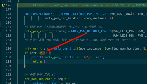
3. A testable and simpler example is as follows:
Best regards,
Peter.Min