This question concerns the description of the SPI communication Electrical Specifications on page 425 of the nRF52840 Product Specification.
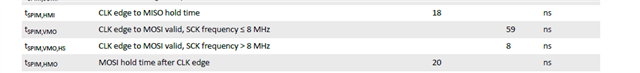
The values for "t_spim_vmo" is stated as 59ns for frequencies below 8MHz and 8ns for frequencies above 8MHz.
If the clock is 8MHz, the time between the falling and rising edges is 62.5ns.
However, a "t_spim_vmo" of 59ns seems too large.
Do the values of 59ns and 8ns switch automatically when the clock frequency is selected?
Or Is it possible to switch it using a register somewhere?
Are there any measurement conditions for the 59ns specification? For example, a wiring capacitance of 100pF?
If the clock is 8MHz and the time between the falling and rising edges is 62.5ns, considering the "t_su (setup time)" of the SPI communication partner circuit,
Since "t_spim_vmo" has a maximum response time of 59ns, there is a possibility that data output may not be completed in time.
Is it okay to use it with an 8MHz clock? And what are the reasons why is it okay?