
Symptoms
Reproduction
The following bare-metal program reproduces the miss on any nRF52805 DK. No softdevice needed; the [155] workaround register is applied explicitly.
Hardware: bridge P0.02 to P0.03 with a wire. Observe P0.02, P0.03, P0.04 on a signal analyzer.
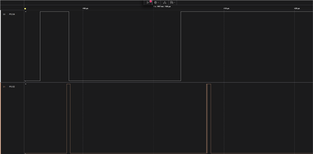
Phase 1 (first 2 s): a single clean 500 ns pulse on P0.02 each cycle. GPIOTE detects every rising edge; P0.04 responds on every cycle.
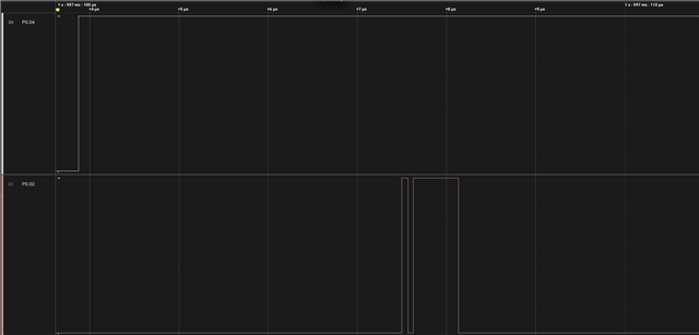
Phase 2 (after 2 s): a 62.5 ns pre-pulse is added immediately before the main pulse. P0.04 stops responding; GPIOTE misses the main pulse rising edge on every cycle.
#include <nrf.h>
#include <nrf_delay.h>

/*
 * nRF52805 GPIOTE edge-detection bug reproducer.
 *
 * Bridge P0.02 -> P0.03 with a wire.
 *
 * TIMER1: 16 MHz, 16-bit, 50 kHz period (CC[2]=319).
 * TIMER0: 16 MHz, 16-bit, cleared each cycle by TIMER1 CC[2] via PPI fork.
 *
 * P0.02 (output): pulse source driven by TIMER0 via PPI.
 * P0.03 (input):  GPIOTE LOTOHI event, bridged to P0.02.
 * P0.04 (output): driven LOW on each detected rising edge, HIGH at period restart.
 *
 * Phase 1 (2s): single 500 ns pulse — P0.04 responds on every cycle.
 * Phase 2:      62.5 ns pre-pulse added before the main pulse —
 *               P0.04 stops responding (GPIOTE misses the main pulse edge).
 *
 * Errata [155]: workaround register written for event channel.
 * Errata [156]: TASKS_CLR[even] replaced with POLARITY_HiToLo + TASKS_OUT[even].
 */

#define PIN_OUT_A  2
#define PIN_IN_B   3
#define PIN_OUT_C  4

#define GPIOTE_CH_A  0   /* task, P0.02 */
#define GPIOTE_CH_B  4   /* event, P0.03, LOTOHI */
#define GPIOTE_CH_C  2   /* task, P0.04 */

#define PPI_CH_PERIOD    0
#define PPI_CH_PRE_SET   1
#define PPI_CH_PRE_CLR   2
#define PPI_CH_DETECT    3
#define PPI_CH_PULSE_SET 4
#define PPI_CH_PULSE_CLR 5

int main(void)
{
    /* GPIO */
    NRF_P0->PIN_CNF[PIN_OUT_A] =
        (GPIO_PIN_CNF_DIR_Output << GPIO_PIN_CNF_DIR_Pos) |
        (GPIO_PIN_CNF_INPUT_Disconnect << GPIO_PIN_CNF_INPUT_Pos) |
        (GPIO_PIN_CNF_DRIVE_S0S1 << GPIO_PIN_CNF_DRIVE_Pos);

    NRF_P0->PIN_CNF[PIN_IN_B] =
        (GPIO_PIN_CNF_DIR_Input << GPIO_PIN_CNF_DIR_Pos) |
        (GPIO_PIN_CNF_INPUT_Connect << GPIO_PIN_CNF_INPUT_Pos) |
        (GPIO_PIN_CNF_PULL_Pulldown << GPIO_PIN_CNF_PULL_Pos);

    NRF_P0->PIN_CNF[PIN_OUT_C] =
        (GPIO_PIN_CNF_DIR_Output << GPIO_PIN_CNF_DIR_Pos) |
        (GPIO_PIN_CNF_INPUT_Disconnect << GPIO_PIN_CNF_INPUT_Pos) |
        (GPIO_PIN_CNF_DRIVE_H0H1 << GPIO_PIN_CNF_DRIVE_Pos);

    /* GPIOTE — [156]: even task channels use HiToLo + TASKS_OUT */
    NRF_GPIOTE->CONFIG[GPIOTE_CH_A] =
        (GPIOTE_CONFIG_MODE_Task << GPIOTE_CONFIG_MODE_Pos) |
        (PIN_OUT_A << GPIOTE_CONFIG_PSEL_Pos) |
        (GPIOTE_CONFIG_POLARITY_HiToLo << GPIOTE_CONFIG_POLARITY_Pos) |
        (GPIOTE_CONFIG_OUTINIT_Low << GPIOTE_CONFIG_OUTINIT_Pos);

    NRF_GPIOTE->CONFIG[GPIOTE_CH_B] =
        (GPIOTE_CONFIG_MODE_Event << GPIOTE_CONFIG_MODE_Pos) |
        (PIN_IN_B << GPIOTE_CONFIG_PSEL_Pos) |
        (GPIOTE_CONFIG_POLARITY_LoToHi << GPIOTE_CONFIG_POLARITY_Pos);

    /* [155]: workaround for double-fire on edges < 1.3 us apart */
    *(volatile uint32_t *)(NRF_GPIOTE_BASE + 0x600 + (4 * GPIOTE_CH_B)) = 1;

    NRF_GPIOTE->CONFIG[GPIOTE_CH_C] =
        (GPIOTE_CONFIG_MODE_Task << GPIOTE_CONFIG_MODE_Pos) |
        (PIN_OUT_C << GPIOTE_CONFIG_PSEL_Pos) |
        (GPIOTE_CONFIG_POLARITY_HiToLo << GPIOTE_CONFIG_POLARITY_Pos) |
        (GPIOTE_CONFIG_OUTINIT_High << GPIOTE_CONFIG_OUTINIT_Pos);

    /* TIMER1: 50 kHz period */
    NRF_TIMER1->MODE      = TIMER_MODE_MODE_Timer;
    NRF_TIMER1->BITMODE   = TIMER_BITMODE_BITMODE_16Bit;
    NRF_TIMER1->PRESCALER = 0;
    NRF_TIMER1->CC[2]     = 319;
    NRF_TIMER1->SHORTS    = TIMER_SHORTS_COMPARE2_CLEAR_Msk;

    /* TIMER0: pulse generator, cleared each cycle */
    NRF_TIMER0->MODE      = TIMER_MODE_MODE_Timer;
    NRF_TIMER0->BITMODE   = TIMER_BITMODE_BITMODE_16Bit;
    NRF_TIMER0->PRESCALER = 0;
    NRF_TIMER0->CC[0]     = 56;   /* pre-pulse HIGH  (62.5 ns wide) */
    NRF_TIMER0->CC[1]     = 57;   /* pre-pulse LOW */
    NRF_TIMER0->CC[2]     = 58;   /* main pulse HIGH (500 ns wide) */
    NRF_TIMER0->CC[3]     = 66;   /* main pulse LOW */

    /* PPI */
    NRF_PPI->CH[PPI_CH_PERIOD].EEP   = (uint32_t)&NRF_TIMER1->EVENTS_COMPARE[2];
    NRF_PPI->CH[PPI_CH_PERIOD].TEP   = (uint32_t)&NRF_GPIOTE->TASKS_SET[GPIOTE_CH_C];
    NRF_PPI->FORK[PPI_CH_PERIOD].TEP = (uint32_t)&NRF_TIMER0->TASKS_CLEAR;

    NRF_PPI->CH[PPI_CH_PRE_SET].EEP = (uint32_t)&NRF_TIMER0->EVENTS_COMPARE[0];
    NRF_PPI->CH[PPI_CH_PRE_SET].TEP = (uint32_t)&NRF_GPIOTE->TASKS_SET[GPIOTE_CH_A];

    NRF_PPI->CH[PPI_CH_PRE_CLR].EEP = (uint32_t)&NRF_TIMER0->EVENTS_COMPARE[1];
    NRF_PPI->CH[PPI_CH_PRE_CLR].TEP = (uint32_t)&NRF_GPIOTE->TASKS_OUT[GPIOTE_CH_A];

    NRF_PPI->CH[PPI_CH_DETECT].EEP  = (uint32_t)&NRF_GPIOTE->EVENTS_IN[GPIOTE_CH_B];
    NRF_PPI->CH[PPI_CH_DETECT].TEP  = (uint32_t)&NRF_GPIOTE->TASKS_OUT[GPIOTE_CH_C];

    NRF_PPI->CH[PPI_CH_PULSE_SET].EEP = (uint32_t)&NRF_TIMER0->EVENTS_COMPARE[2];
    NRF_PPI->CH[PPI_CH_PULSE_SET].TEP = (uint32_t)&NRF_GPIOTE->TASKS_SET[GPIOTE_CH_A];

    NRF_PPI->CH[PPI_CH_PULSE_CLR].EEP = (uint32_t)&NRF_TIMER0->EVENTS_COMPARE[3];
    NRF_PPI->CH[PPI_CH_PULSE_CLR].TEP = (uint32_t)&NRF_GPIOTE->TASKS_OUT[GPIOTE_CH_A];

    NRF_PPI->CHENSET = (1 << PPI_CH_PERIOD) |
                       (1 << PPI_CH_DETECT) |
                       (1 << PPI_CH_PULSE_SET) |
                       (1 << PPI_CH_PULSE_CLR);

    NRF_POWER->TASKS_CONSTLAT = 1;

    NRF_TIMER0->TASKS_CLEAR = 1;
    NRF_TIMER1->TASKS_CLEAR = 1;
    NRF_TIMER0->TASKS_START = 1;
    NRF_TIMER1->TASKS_START = 1;

    /* Phase 1: single 500 ns pulse, ~2 s */
    nrf_delay_ms(2000);

    /* Phase 2: enable pre-pulse — bug triggers */
    NRF_PPI->CHENSET = (1 << PPI_CH_PRE_SET) | (1 << PPI_CH_PRE_CLR);

    while (1) {}
}
What to look for on the analyzer
Phase 1 — working:
P0.02: ___|‾‾‾‾‾|_________________  (500 ns pulse)
P0.03: ___|‾‾‾‾‾|_________________  (same, bridged)
P0.04: ‾‾‾‾|_______|‾‾‾‾‾‾‾‾‾‾‾‾‾  (responds to every edge)

Phase 2 — bug:
P0.02: ____|‾|_|‾‾‾‾‾‾‾|__________  (62.5 ns pre-pulse + 500 ns main pulse)
P0.03: ____|‾|_|‾‾‾‾‾‾‾|__________  (same, bridged)
P0.04: ‾‾‾‾‾‾‾‾‾‾‾‾‾‾‾‾‾‾‾‾‾‾‾‾‾‾  (locked HIGH — main edge missed)
Workaround
Adding hysteresis in hardware so that the pre-pulse does not exist.