I CANNOT USE nPM 2100 EK WITH CR2023

Hello

nPM Power UP v 2.24 detects nPM2100 EK, but does not detect the CR2032 battery.
The active battery model selected is CR2032 and the fuel gauge is enabled.

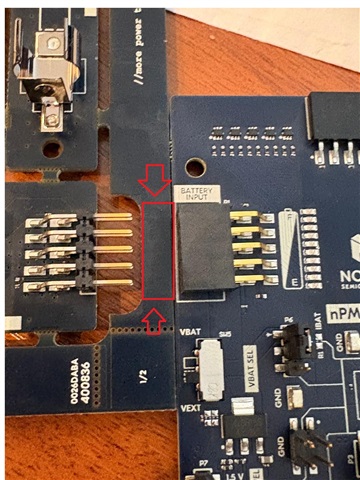
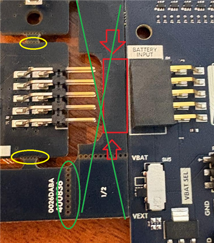
I placed the CR2032 in the battery holder and connected it to Battery Input Connector on EK.

Two LEDs light up side by side: a red LED and a yellow LED.

I tested it with SW5 for VEXT and VBAT.

I have read this link.www.nordicsemi.com/.../Get-started

Regards

Luiz Miranda

Parents Reply Children
  • Hi Szabolcs:

    It's very easy, but I haven't read anything about the breaking procedure in other documentation.
    Again, thank you!!

    What is the best way to connect a CR2450 to the add-board?

    Luiz

  • Hi Luiz,

    I'm glad to hear that it works. I'm afraid we don't have a ready solution to connect CR2450 to the EK. I think the best way would be to buy a battery holder and use jumper wires to connect to the input. You can use the CR2032 fuel gage model, as the chemistry of these batteries are identical.

  • Hi Szabolcs:

    I'm having trouble putting together an electrical schematic (components) to use the CR2032 with a piezo buzzer. The buzzer will sound 7 times a day for 10 seconds each time. Can Nordic help me find a solution?

  • Hi Luiz,

    we can help, yes. What exactly is the problem, where did you get stuck? Can you share the schematic? 

  • Hi Szabolcs:

    We are developing a new commercial product based on the nRF54L15 SoC and managed by the nPM2100 PMIC. The device is powered by a CR2032 coin cell battery and features a critical acoustic alarm function using an externally driven passive piezoelectric transducer.

    The piezo transducer we intend to use is:

    Piezo element, Externally driven, Frequency: 4,0 kHz - 5,0 kHz, Voltage - Input (Max): 30V p-p, Impedance: 250 Ohms, Capacitance @ Frequency: 16000pF @ 120Hz, Size / Dimension: 1.063" Dia (27.00mm), Termination: Wire Leads (100 mm lead wire)

     Observed Behavior & Test Setup:

    We conducted bench tests using the nPM2100 EK powered by a brand new CR2032 battery (open-circuit voltage of 3.19V). We monitored the real-time power system metrics using the nPM Power UP tool within nRF Connect for Desktop.

    The PMIC output ($V_{OUT}$) was configured to 3.0V. For the physical evaluation, we utilized a small reference PCB that already integrated the exact same passive cylindrical transducer we aim to qualify. Originally, this reference PCB is powered by 3x LR44 alkaline batteries (~4.5V), but we could not fully identify its discrete electronic driver components.

    We modified this reference board to be powered directly by the 3.0V output from the nPM2100 EK. Upon triggering the alarm, the sound pressure level was loud and successfully met our target of 80 dB.

    However, during this activation, we observed a severe voltage sag on the CR2032 battery due to the high internal impedance of the lithium cell. The CR2032 voltage dropped instantly to 1.89V during the first prolonged audio pulse, recovering very slowly after the pulse ended. In subsequent tests with the rail capacitors fully charged, the voltage drop stabilized at 2.65V. Additionally, we found that this reference board circuit completely fails to drive the buzzer if the nPM2100 $V_{OUT}$ is configured anywhere below 3.0V.

    Our Objective:

    Since the passive transducer requires an external oscillating signal and our final product will not use this external reference PCB, we plan to generate the 4 kHz to 5 kHz frequency directly using the nRF54L15 PWM peripheral. We need to design our own discrete driver circuit on our custom PCB to guarantee the same 80 dB output efficiently, without triggering a brownout reset (BOD) on the nRF54L15.

    Our Questions for Support:

    What are the official recommendations for the driver circuit topology (e.g., migrating to an N-channel MOSFET like the 2N7002, an H-bridge configuration, or sticking with a standard BJT) to safely and efficiently achieve 80 dB at 3.0V or below?

     What are the ideal values and types of bulk/decoupling capacitors (low-ESR ceramic vs. electrolytic) recommended to shield the nPM2100 power rail from the heavy current ripples caused by the 4 kHz piezo PWM switching?

     Are there any specific application notes or reference designs from Nordic combining the nPM2100 and passive piezo transducers operating on high-impedance coin cells (CR2032)? 

    Is it possible to achieve a minimum of 80dB with the CR2032? If not, which battery would be best? CR2450, for example CR2450?

    An important point of reference is that the PCB will have an antenna chip and that we are aiming for a PCB with dimensions of 4.5 cm x 3.00 cm.

    I have nRF54L15 DK, nPM2100 EK and Power Profiler kit II to make tests on protoboard.

    Thank you in advance for your time and technical support during our project development.

    Best regards,

Related