Need urgent technical support for Nordic PMIC PM1300

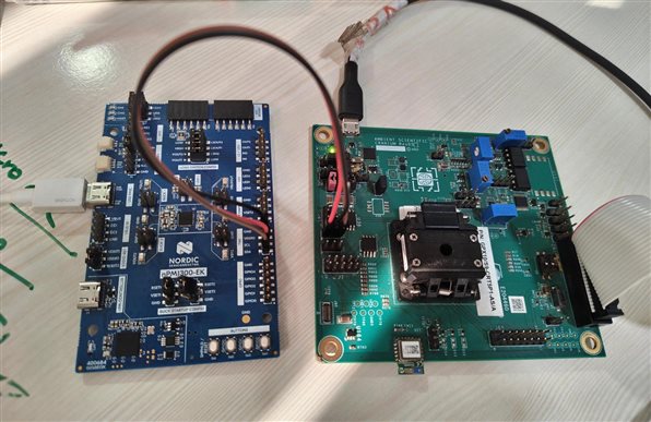
we are using nPM1300 EVK board for an upcoming project we are trying to interface PMIC PM1300 chip with Ambient Scientific processor GPx10 Pro.

It will be a huge setback for our project that is under development, if the I2C Interface between the two chips don’t work… since proto boards are already in fabrication


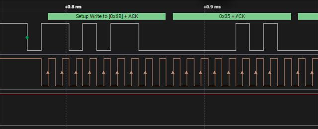
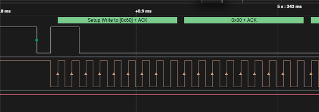
We have tested GPx10Pro I2C interface extensively with other sensors… but with this PMIC it is inconsistent and unreliable.  And this is the only part of Hardware that is not working yet.

In bare metal code, we are able to get acknowledgement sometimes. 

Parents
  • Hi,

    As the I2C communication sometimes work but is unreliable the first thing that comes to mind is if you have long jumper wires when testing, perhaps combined with too weak pull-up resistors? I would suggest shortening the wires and using stronger (lower resistance) pull resistors.

  • Hi,

    we have tried with other pull up resistors still getting same results. we will once check by soldering the PMIC i2c pins with our mcu and will let you know the results.

  • Hi,

    I see. To get a full and consise overview, can you share a photo of your current complete setup showing how both boards are powere, and the jumpwer configuration on the nPM EK? We need to ensure that both devices has the same VDD(IO) voltage. Can you also show a oscillioscope trace of both SDL and SDA in the same trace?

    If the nPM EK is powered, configured correctly for the setup (so that the voltages are the same on both sides), and you write to it with the correct address (which I see you do from a previosu logic analyser trace), the nPM shoudl have acknliwledged. Is it still the case that it does work (at least you get the ack) about 8 out of 10 times? So the issue is stil intermittent?

  • Hi,

    please find the setup image below

    we facing some difficulty to capture both SDA and SCL at a time. we will send those ASAP. this is the whole setup please check once.

  • Hi,

    We are observing intermittent behavior on the I²C bus. In some cases, we receive the ACK response correctly; however, at other times the SDA line remains stuck low and does not return high. After performing approximately 2 to 4 reset cycles, the SDA line is released and returns to the high state, after which communication resumes normally.

    SDA going low:

  • Hi,

    This looks fairly good I think. You have VDDIO to VOUT2, and from the photo it looks like RSET2 is shorted to VSET2 (see Buck startup configuration), so the startup voltage should be 3.0V. I would assume that should be OK, but you could replace the resistor to get 3.3V as you write your MCU uses (see VSET).

    Were you able to get new measurement where wee see both the clock and data line?

  • Hi,

    Can you double check (measure) the VDDIO voltage levels on both sides and show here so that we see clear evidence that you are using the same level? There is no VDDIO connection between the two boards, so you need to configure the same voltage on both ends. If that is not the case, and for instance the VDDIO voltage on the MCU is significantly lower, it could be that the logical 1 is in an undefined range seen from the nPM, in which case it could be expdected that comminication sometimes works, and sometimes fails. This is a key factor that shoudl be properly understood.

    Also, are there any level shifters or similar between the nPM and MCU (I do not know what the MCU board contains in the signal path). Any information on that could be usefull.

    The plot from June 2nd, can you confirm that it was measured on the nPM side?

    If the voltage level is the same on both the nPM and MCU we need to look closer, and then I would re-iterate the ask for a oscillioscope (analog) plot close to the nPM that shows both SDA and SCL (not just a logic analyzer plot, as that does not show us any information about the signal integrity).

Reply
  • Hi,

    Can you double check (measure) the VDDIO voltage levels on both sides and show here so that we see clear evidence that you are using the same level? There is no VDDIO connection between the two boards, so you need to configure the same voltage on both ends. If that is not the case, and for instance the VDDIO voltage on the MCU is significantly lower, it could be that the logical 1 is in an undefined range seen from the nPM, in which case it could be expdected that comminication sometimes works, and sometimes fails. This is a key factor that shoudl be properly understood.

    Also, are there any level shifters or similar between the nPM and MCU (I do not know what the MCU board contains in the signal path). Any information on that could be usefull.

    The plot from June 2nd, can you confirm that it was measured on the nPM side?

    If the voltage level is the same on both the nPM and MCU we need to look closer, and then I would re-iterate the ask for a oscillioscope (analog) plot close to the nPM that shows both SDA and SCL (not just a logic analyzer plot, as that does not show us any information about the signal integrity).

Children
Related