How to reach datasheet-level 2.9 µA System ON IDLE current on nRF54L15 DK with NCS Matter sample?

We are planning to use the nRF54L15 for a Matter over Thread product, so we are currently evaluating the low-power performance of this device.

According to the nRF54L15 product specification / datasheet, the sleep current for:

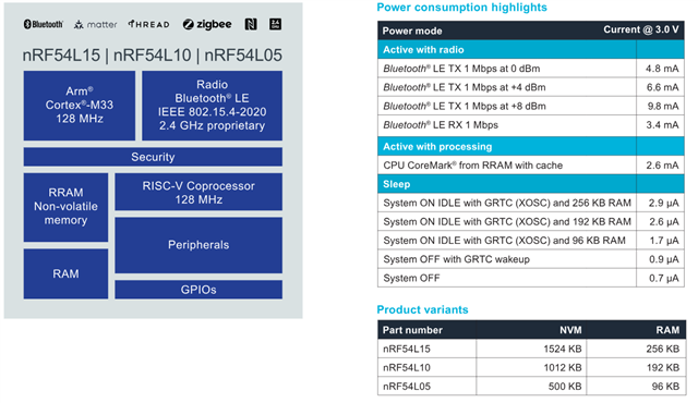
is listed as approximately 2.9 µA. Since the nRF54L15 has 256 KB RAM, I expected that it should be possible to observe a sleep current close to this value under the proper low-power configuration.

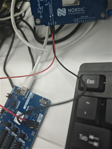
I used the following setup for the test:
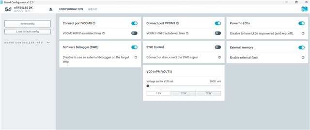
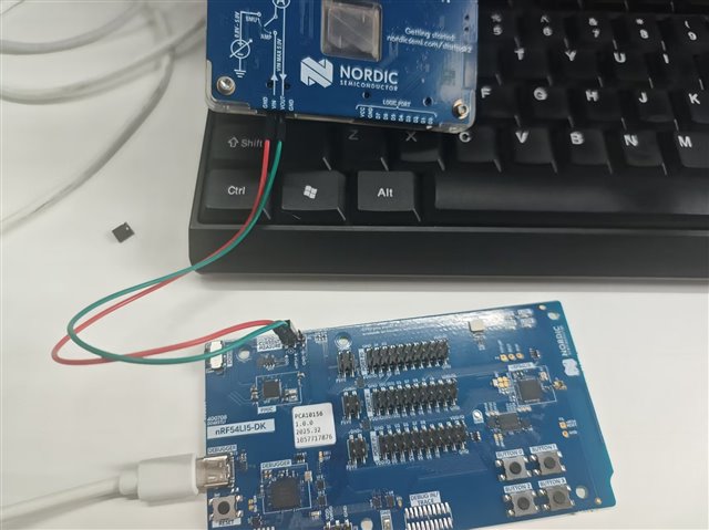
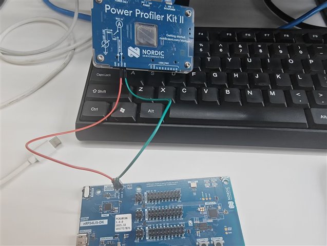
  • Board: nRF54L15 DK
  • Chip: nRF54L15
  • SDK: nRF Connect SDK v3.2.1
  • Sample: nrf/samples/matter/window_covering
  • Build command:  west build -b nrf54l15dk/nrf54l15/cpuapp -p always -- -DCONF_FILE=prj_release.conf
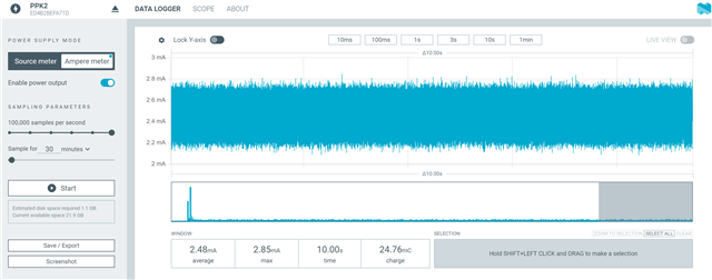
  • Measurement tool: Nordic PPK
  • Measurement mode: Ammeter mode
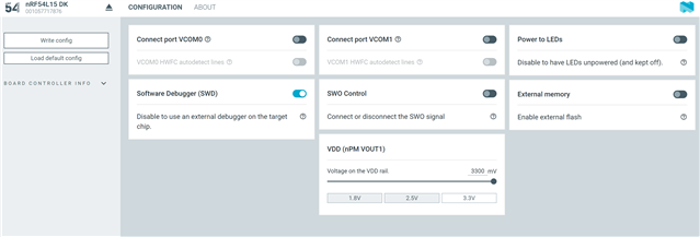
  • Measurement point: VDD CURRENT MEASURE on the nRF54L15 DK

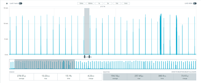
Test 1: Original sample without modifications

First, I built and flashed the sample using the original prj_release.conf without any modifications.

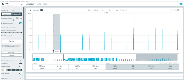
In this case, the measured baseline current was about 194.18 µA.

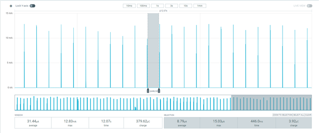
Test 2: After disabling shell/banner/early console

I suspected that some UART/logging-related functionality might still be enabled, so I added the following configurations to prj_release.conf:

CONFIG_CHIP_LIB_SHELL=n
CONFIG_NCS_BOOT_BANNER=n
CONFIG_BOOT_BANNER=n
CONFIG_EARLY_CONSOLE=n

After adding the above configurations, I rebuilt and flashed the application again.

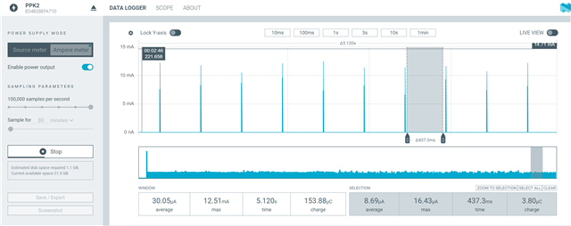
The measured baseline current dropped significantly, and the lowest current I observed was about 8.79 µA.

This is much better than the original result, but it is still higher than the 2.9 µA value listed in the datasheet for System ON IDLE with GRTC and 256 KB RAM.

Questions

  1. Is it expected that the Matter window_covering sample on the nRF54L15 DK cannot reach the datasheet-level System ON IDLE current of around 2.9 µA without further modifications?
  2. What are the remaining contributors that may keep the current at around 8.8 µA in this sample? For example, could this be caused by Thread/Matter timers, enabled peripherals, DK board circuitry, retained RAM configuration, logging backend, UART state, or other subsystems?
  3. What additional project configuration changes, device tree changes, or board-level settings are required in order to observe a sleep current close to 2.9 µA on the nRF54L15 DK?
  4. Is there a recommended minimal low-power sample or reference configuration for measuring the lowest System ON IDLE current on nRF54L15?

Thanks.

Parents
  • Hello,

    Sorry I have not addressed the current consumption when this is set as CONFIG_NCS_SAMPLE_MATTER_WATCHDOG=n in my previous replyy.

    I have tried the following config according to this devacademy course (Reducing power consumption in Matter - Nordic Developer Academy)

    CONFIG_NCS_SAMPLE_MATTER_WATCHDOG=n
    CONFIG_NCS_SAMPLE_MATTER_LEDS=n
    CONFIG_RAM_POWER_DOWN_LIBRARY=y

    I got average current 2.49uA. 

     ''For low-power measurement of the Matter window_covering sample on the nRF54L15 DK, could you please suggest whether these two options should be enabled or disabled?'' According to the devacademy matter course, these are the configs (mentioned above) to get reduced sleep current along with zephyr system power management configs (CONFIG_POWEROFF=y and CONFIG_PM=y). I measured this with when device is commissioned. I have also checked the ampere meter mode and it's around 2.57uA.

    I think the spike you are seeing is abnormal and it may be PPK artifact or measurement error. When device communicate with matter network I can see a spike which is around 9 mA and that's in the range when radio is active. Seeing 300mA is very abnormal. 

    Regarding the Board Configurator app, I don't have the SWO control and External Memory option for nRF54L15 DK (V0.9.2). Which version of DK you are using? But I tried with nRF54LM20, then I can see these options. I am not sure if it is related to DK version. I will check with team. 

    Thanks.

    BR

    Kazi

  • Hi Kazi,

    Thanks for sharing the sample zip file.

    I did some tests today using the firmware you provided. I flashed the merged.hex file from the build directory directly to my nRF54L15 DK.

    For the commissioning test, I used Apple Home app together with a HomePod. The device could be commissioned successfully in one of the test setups described below.

    Test 1: Default Board Configurator settings + PPK ammeter mode

    First, I kept the default Board Configurator settings on my side.

    I used PPK in ammeter mode, measuring through the current measurement path on the DK. The wiring was as shown below.

    With this setup, the device could be commissioned successfully using Apple Home app + HomePod.

    However, after commissioning, the measured sleep baseline current was still around 8.x µA. I could not observe the 2.5–4.1 µA level shown in your measurement.

    So with the firmware you provided, my result is still different from your result when using my default board configuration and PPK ammeter mode.

    Test 2: Modified Board Configurator settings + PPK ammeter mode

    Then I modified the Board Configurator settings according to your previous guidance and screenshot.

    I still used PPK in ammeter mode for this test.

    After this change, the behavior became abnormal. After power-up, the current stayed at the mA level continuously. I could not observe the typical low-power sleep/wakeup current waveform. Also, the firmware did not seem to work normally, and the device could not be commissioned.

    Test 3: Modified Board Configurator settings + PPK source meter mode

    Finally, I changed the measurement method to PPK source meter mode and enabled a 3.3 V supply output from the PPK.

    The wiring was as shown below.

    However, the result was similar to Test 2. The current stayed at the mA level after power-up, I could not see the expected sleep/wakeup current waveform, and the firmware did not work normally or enter commissioning successfully.

    Summary

    Based on my current tests, it seems that only when I keep the default Board Configurator settings and use PPK in ammeter mode, the firmware on the DK can work normally and the device can be commissioned successfully. But in that case, the measured sleep baseline current is still around 8.x µA, which is different from your result.

    Could you please help check whether my wiring method, Board Configurator settings, or measurement method may be wrong?

    Also, could you please provide more detailed guidance on how to correctly configure the nRF54L15 DK and connect the PPK in order to reproduce your low-current measurement result?

    I will continue testing the watchdog-disabled configuration according to your latest suggestion and will update that result separately later.

    Thanks.

Reply
  • Hi Kazi,

    Thanks for sharing the sample zip file.

    I did some tests today using the firmware you provided. I flashed the merged.hex file from the build directory directly to my nRF54L15 DK.

    For the commissioning test, I used Apple Home app together with a HomePod. The device could be commissioned successfully in one of the test setups described below.

    Test 1: Default Board Configurator settings + PPK ammeter mode

    First, I kept the default Board Configurator settings on my side.

    I used PPK in ammeter mode, measuring through the current measurement path on the DK. The wiring was as shown below.

    With this setup, the device could be commissioned successfully using Apple Home app + HomePod.

    However, after commissioning, the measured sleep baseline current was still around 8.x µA. I could not observe the 2.5–4.1 µA level shown in your measurement.

    So with the firmware you provided, my result is still different from your result when using my default board configuration and PPK ammeter mode.

    Test 2: Modified Board Configurator settings + PPK ammeter mode

    Then I modified the Board Configurator settings according to your previous guidance and screenshot.

    I still used PPK in ammeter mode for this test.

    After this change, the behavior became abnormal. After power-up, the current stayed at the mA level continuously. I could not observe the typical low-power sleep/wakeup current waveform. Also, the firmware did not seem to work normally, and the device could not be commissioned.

    Test 3: Modified Board Configurator settings + PPK source meter mode

    Finally, I changed the measurement method to PPK source meter mode and enabled a 3.3 V supply output from the PPK.

    The wiring was as shown below.

    However, the result was similar to Test 2. The current stayed at the mA level after power-up, I could not see the expected sleep/wakeup current waveform, and the firmware did not work normally or enter commissioning successfully.

    Summary

    Based on my current tests, it seems that only when I keep the default Board Configurator settings and use PPK in ammeter mode, the firmware on the DK can work normally and the device can be commissioned successfully. But in that case, the measured sleep baseline current is still around 8.x µA, which is different from your result.

    Could you please help check whether my wiring method, Board Configurator settings, or measurement method may be wrong?

    Also, could you please provide more detailed guidance on how to correctly configure the nRF54L15 DK and connect the PPK in order to reproduce your low-current measurement result?

    I will continue testing the watchdog-disabled configuration according to your latest suggestion and will update that result separately later.

    Thanks.

Children
No Data
Related