Different LTE-M current consumption behaviors and RAI inactivity handling on nRF9151

Hello,

We are currently performing power consumption measurements on the Nordic nRF9151 using the PPK2 in LTE-M with an Objenious SIM card.

During our tests, we observed two different network behaviors leading to significantly different current consumption profiles, even when running exactly the same test scenario.

1. Different network attach behaviors and current consumption

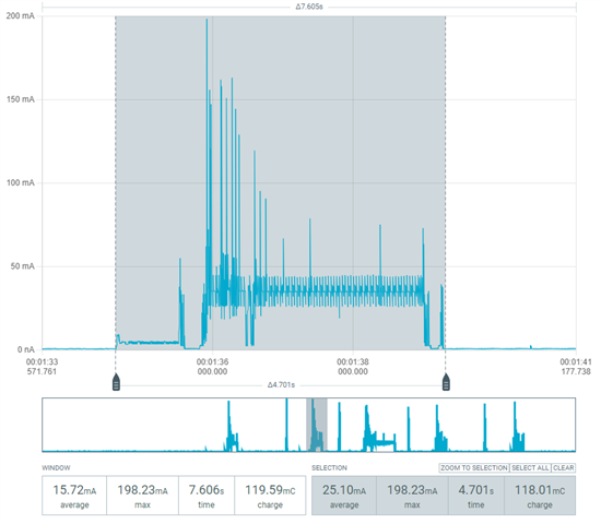
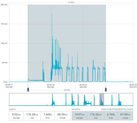
The attached screenshots correspond to:

  • Same firmware
  • Same LTE-M configuration
  • Same SIM card
  • Same location and radio conditions
  • Same test procedure

The test simply consists of:

  1. Setting CFUN=1
  2. Waiting for network registration
  3. Repeating the same attach sequence again a few seconds later without changing any parameter

Despite this, we observe two different attach behaviors with very different energy consumption, in some cases almost double.

Logs: 

[2026-05-26 09:56:37.039] at+cfun=1
[2026-05-26 09:56:37.897]
[2026-05-26 09:56:37.898] OK
[2026-05-26 09:56:38.982]
[2026-05-26 09:56:38.982] +CEREG: 2,"E485","093F9E11",7
[2026-05-26 09:56:40.786]
[2026-05-26 09:56:40.786] +CEREG: 1,"E485","093F9E11",7,,,"11100000","11100000"
[2026-05-26 09:56:47.918] at+cfun=0
[2026-05-26 09:56:49.870] +CEREG: 1,"E485","093F9E10",7,,,"11100000","11100000"
[2026-05-26 09:56:54.306]
[2026-05-26 09:56:54.788]
[2026-05-26 09:56:54.788] OK
[2026-05-26 09:56:54.788]
[2026-05-26 09:56:54.788] +CEREG: 0
[2026-05-26 09:56:57.621] at+cereg=5
[2026-05-26 09:56:58.961]
[2026-05-26 09:56:58.962] OK
[2026-05-26 09:57:02.461] at+cfun=1
[2026-05-26 09:57:03.198]
[2026-05-26 09:57:03.198] OK
[2026-05-26 09:57:04.593]
[2026-05-26 09:57:04.593] +CEREG: 2,"E485","093F9E10",7
[2026-05-26 09:57:05.015]
[2026-05-26 09:57:05.015] +CEREG: 1,"E485","093F9E10",7,,,"11100000","11100000"
[2026-05-26 09:57:15.791] at+cfun=0
[2026-05-26 09:57:22.234]
[2026-05-26 09:57:22.234] OK
[2026-05-26 09:57:22.236]
[2026-05-26 09:57:22.236] +CEREG: 0
[2026-05-26 09:57:26.291] at+cereg=5
[2026-05-26 09:57:27.091]
[2026-05-26 09:57:27.091] OK
[2026-05-26 09:57:29.946] at+cfun=1
[2026-05-26 09:57:30.901]
[2026-05-26 09:57:30.901] OK
[2026-05-26 09:57:32.098]
[2026-05-26 09:57:32.098] +CEREG: 2,"E485","093F9E10",7
[2026-05-26 09:57:32.508]
[2026-05-26 09:57:32.508] +CEREG: 1,"E485","093F9E10",7,,,"11100000","11100000"
[2026-05-26 09:57:41.527] at+cops?*
[2026-05-26 09:57:46.284]
[2026-05-26 09:57:46.284] +COPS: 0,2,"20820",7
[2026-05-26 09:57:46.286]
[2026-05-26 09:57:46.288] OK
[2026-05-26 09:58:36.929] AT%XSYSTEMMODE?
[2026-05-26 09:58:38.099]
[2026-05-26 09:58:38.099] %XSYSTEMMODE: 1,0,0,0
[2026-05-26 09:58:38.105]
[2026-05-26 09:58:38.105] OK

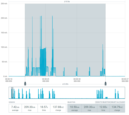
We also observe similar behavior differences during:

  • UDP transmissions
  • DTLS handshake procedures

However, with other operators (for example Orange), we do not observe these differences, which makes us think this could be related to operator-side LTE-M configuration or network behavior.

Could you please help us understand:

  • What LTE-M signaling or network procedures could explain these differences?

2. RAI behavior and inactivity timer reduction in NB-IoT protocol

We are also testing RAI behavior on the nRF9151 in order to reduce the inactivity time after UDP transmissions.

We enabled RAI using:

AT%RAI=2

Relevant logs:

AT%RAI=2
OK

AT+CFUN=1
OK

+CEREG: 2,"C3D1","093F9ED8",9

%RAI: "093F9ED8","20820",0,1

+CEREG: 1,"C3D1","093F9ED8",9,,,"11100000","11100000"

From the %RAI notification, it seems that:

  • AS-RAI is disabled by the network
  • CP-RAI is enabled

Based on our understanding, CP-RAI should reduce the inactivity time after uplink UDP transmissions in NB-IoT protocol.

We verified this behavior with another modem platform, where enabling CP-RAI effectively reduces the inactivity duration.

However, on the nRF9151, enabling:

AT%RAI=2

does not seem to change the inactivity duration or current consumption behavior after UDP transmissions.

Could you please confirm:

  1. Is AT%RAI=2 the correct command to enable CP-RAI on nRF9151 for UDP traffic?
  2. Is there a modem trace or debug method allowing us to verify whether the RAI indication is actually transmitted and accepted by the network?

Thank you.

Parents
  • Hi,

    Thank you for the detailed description. I will be addressing both of your questions.

    1. Different LTE-M power profiles

    Your attach logs show LTE-M (AcT = 7), but the cell ID differs between runs (093F9E11 vs 093F9E10). Different cells can use different network settings (for example cDRX and the RRC inactivity timer, which can vary between cells even on the same operator), which affects how long the modem stays in RRC Connected after activity. This looks like expected operator/cell behavior. The main procedures involved are RRC connection setup/reconfiguration (where the network sets these parameters), time in RRC Connected, and RRC release back to Idle.

    To confirm on future runs, please enable AT+CSCON=1 before AT+CFUN=1, this will show how long the modem stays in RRC Connected. Optionally, capturing a modem trace would show the timer/cDRX values the network applied.

    2. RAI after UDP on NB-IoT

    Your RAI log shows NB-IoT (AcT = 9). AT%RAI=2 is correct on mfw 2.0.2 to enable RAI and receive %RAI notifications however it does not apply RAI to a specific UDP send. Also CP-RAI is enabled by the network, but AS-RAI is not. For user-plane UDP, AS-RAI is usually more effective at shortening the connected period. With AS-RAI disabled on this network, the benefit from RAI may be limited.

    The key point is that AT%RAI=2 alone does not apply RAI to a UDP packet. You must also signal last data via a socket RAI option on the final send for a single uplink UDP with no further data, that would typically be NRF_RAI_LAST (in code) or AT#XSOCKETOPT (with Serial Modem application). Without that signal, the network uses its normal inactivity timer, which explains the long tail in your capture. Even when RAI is set correctly, the network may still keep the connection open.

    You mentioned AT commands only via Tera Term with no custom nRF Connect SDK application. Could you confirm whether Serial LTE Modem (SLM) is flashed on the device? Per-packet RAI is set through socket commands such as  AT#XSOCKET but it is a SLM command, not native modem AT command. If SLM is not used, raw AT commands alone cannot set per-packet RAI so you would need either the SLM sample from nRF Connect SDK or a minimal application using nrf_setsockopt() with NRF_RAI_LAST / NRF_RAI_NO_DATA.

    Best Regards,
    Syed Maysum

  • Hi,

    Thank you for the detailed explanation.

    Regarding the first point, your explanation about the different Cell IDs and possible differences in network configuration (RRC inactivity timer, cDRX, etc.) makes sense and could explain the different power consumption profiles that we observe. 

    Regarding the RAI topic, I am using the following socket commands for my UDP/DTLS tests:

    AT#XSSOCKET=1,2,0,1001
    AT#XCONNECT="<server>",<port>
    AT#XSEND="<data>"
    

    I did not flash the device myself, so I am not completely sure which firmware is running on it. However, these commands are available and are used for all of my tests.

    From your explanation, it sounds like I may be using SLM or a firmware derived from SLM.

    I checked the SLM documentation for #XSOCKET and #XSOCKETOPT, but I could not find any socket option related to RAI, NRF_RAI_LAST, or NRF_RAI_NO_DATA.

    Could you please confirm:

    • Whether the availability of #XSSOCKET, #XCONNECT, and #XSEND indicates that SLM is running on the device?

    • If SLM is being used, is there an AT command that allows setting per-packet RAI (NRF_RAI_LAST / NRF_RAI_NO_DATA)?

    • If not, is a custom nRF Connect SDK application required to test RAI properly on UDP/DTLS traffic?

    Thank you.

Reply
  • Hi,

    Thank you for the detailed explanation.

    Regarding the first point, your explanation about the different Cell IDs and possible differences in network configuration (RRC inactivity timer, cDRX, etc.) makes sense and could explain the different power consumption profiles that we observe. 

    Regarding the RAI topic, I am using the following socket commands for my UDP/DTLS tests:

    AT#XSSOCKET=1,2,0,1001
    AT#XCONNECT="<server>",<port>
    AT#XSEND="<data>"
    

    I did not flash the device myself, so I am not completely sure which firmware is running on it. However, these commands are available and are used for all of my tests.

    From your explanation, it sounds like I may be using SLM or a firmware derived from SLM.

    I checked the SLM documentation for #XSOCKET and #XSOCKETOPT, but I could not find any socket option related to RAI, NRF_RAI_LAST, or NRF_RAI_NO_DATA.

    Could you please confirm:

    • Whether the availability of #XSSOCKET, #XCONNECT, and #XSEND indicates that SLM is running on the device?

    • If SLM is being used, is there an AT command that allows setting per-packet RAI (NRF_RAI_LAST / NRF_RAI_NO_DATA)?

    • If not, is a custom nRF Connect SDK application required to test RAI properly on UDP/DTLS traffic?

    Thank you.

Children
No Data
Related