Hello everyone,
I have tried several different approaches to solve this issue, but I have not been successful so far.
My goal is to generate an interrupt when the LIS2MDL magnetic field measurements (X, Y, and Z) go below a defined threshold. I created a small test application (shown below) to verify the interrupt functionality.
I have experimented with many different threshold values, including very low and very high settings, but the interrupt is never triggered.
Has anyone successfully used the LIS2MDL threshold interrupt feature with Zephyr or the nRF5340? Am I missing a required configuration step, such as interrupt routing, GPIO configuration, or sensor initialization?
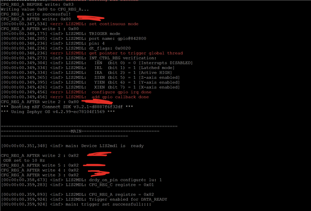
Alsi "I'm having an doubt verifying if a trigger was successfully programmed on the sensor. When I configure it like this:
The function always returns success (ret == 0), even when I set a trigger type that the sensor theoretically doesn't support. I have no way to verify if the trigger was actually applied or just silently ignored by the driver."
my code ::
````
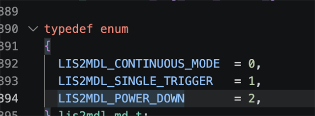
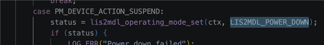
Driver code ::
Any suggestions would be greatly appreciated.
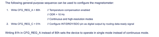
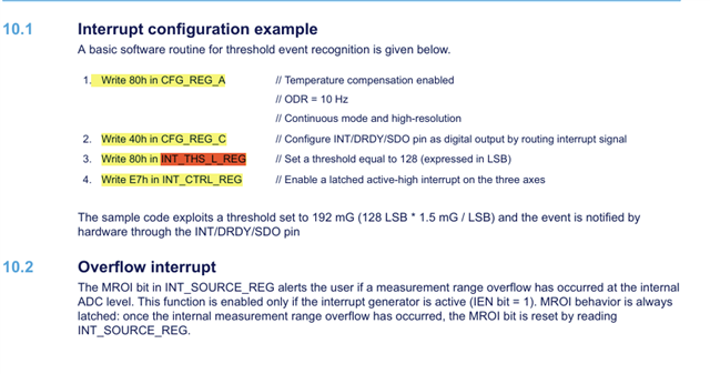
To configure a trigger mode i applied this configuration as say in the datasheet but no respone ::
`````
Thank you.