Regarding Matching Network NRF54L15

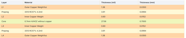
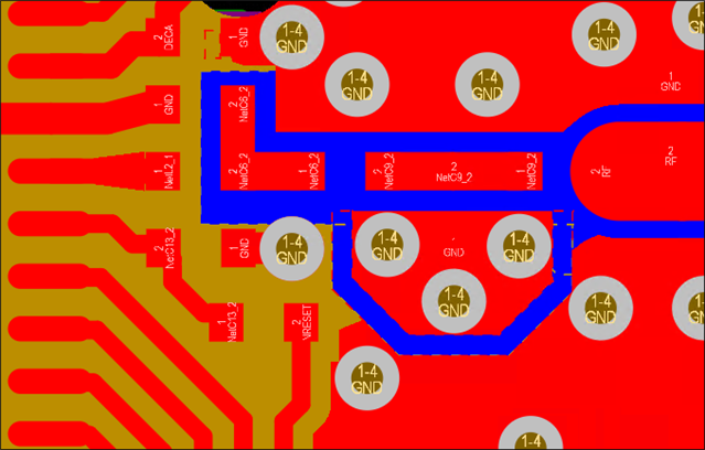
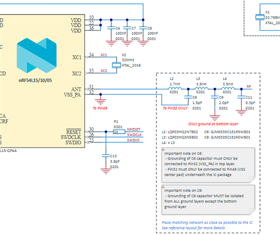
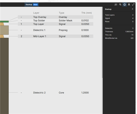
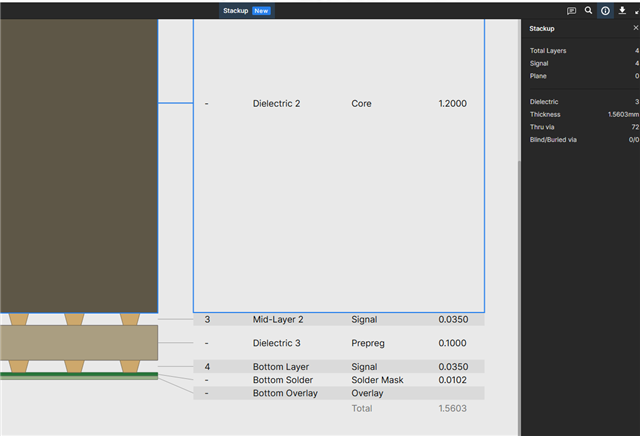
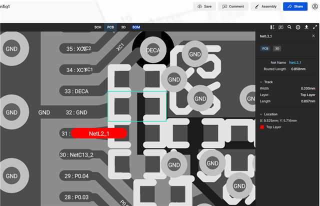
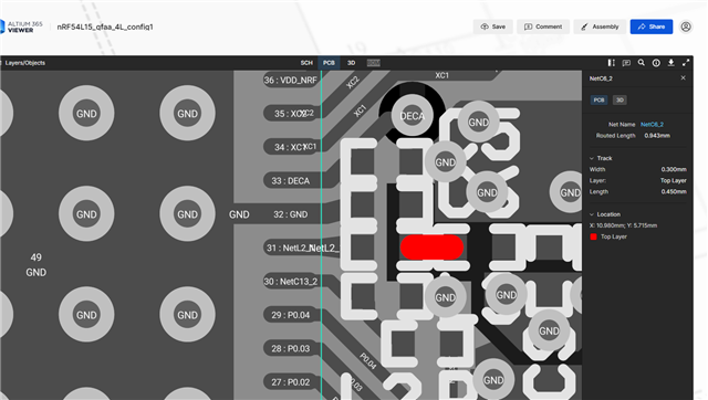
So I have two questions. My first is on the impedance matching network on different pcb stackups. So wouldn't I need a different matching network for a different pcb stackup? The reference design uses a 1.6mm board with 4.6 dielectric constant. While I'm using a 1mm board with 4.5 dielectric constant. Is there way I can do simulations before manufacturing the pcb? Second question is why are the widths different for the traces in the impedance matching network? Like it goes from 0.2mm to 0.27mm to 0.3mm. Why 0.3mm. I get why transmission trace is 0.762 because that is 50 ohms for the pcb stackup.


Parents
  • Hi,

    My first is on the impedance matching network on different pcb stackups. So wouldn't I need a different matching network for a different pcb stackup? The reference design uses a 1.6mm board with 4.6 dielectric constant. While I'm using a 1mm board with 4.5 dielectric constant. Is there way I can do simulations before manufacturing the pcb?

    The values of the matching network may need to be tweaked for the thinner board. However this must be determined by measuring the RF performance of the board once produced, so as a starting point the values in the reference schematic should be used.

    It's unfortunately not easy/possible to simulate this beforehand. A full wave simulation is needed, and for usable results a model of the internal structure of the nRF54L15 is needed, which is not something we provide.

    Second question is why are the widths different for the traces in the impedance matching network? Like it goes from 0.2mm to 0.27mm to 0.3mm. Why 0.3mm. I get why transmission trace is 0.762 because that is 50 ohms for the pcb stackup.

    The trace widths within the matching network is selected to match the pad widths. 0.2mm is the width of the pads on the nRF54L15, while 0.27mm is the width of the pads for the 0201 components. 

    The trace between the ANT pin and L2 is also tapering out to 0.27mm to match the pad width.

    Matching the traces to the width of the pads helps with minimizing reflections due to sudden changes in width at the pads.

    Since the ANT pin isn't 50 Ohm the 50 Ohm reference point is at the end of the matching network, so the traces within does not need to have impedance of 50 Ohm.

    Best regards,

    Bendik

Reply
  • Hi,

    My first is on the impedance matching network on different pcb stackups. So wouldn't I need a different matching network for a different pcb stackup? The reference design uses a 1.6mm board with 4.6 dielectric constant. While I'm using a 1mm board with 4.5 dielectric constant. Is there way I can do simulations before manufacturing the pcb?

    The values of the matching network may need to be tweaked for the thinner board. However this must be determined by measuring the RF performance of the board once produced, so as a starting point the values in the reference schematic should be used.

    It's unfortunately not easy/possible to simulate this beforehand. A full wave simulation is needed, and for usable results a model of the internal structure of the nRF54L15 is needed, which is not something we provide.

    Second question is why are the widths different for the traces in the impedance matching network? Like it goes from 0.2mm to 0.27mm to 0.3mm. Why 0.3mm. I get why transmission trace is 0.762 because that is 50 ohms for the pcb stackup.

    The trace widths within the matching network is selected to match the pad widths. 0.2mm is the width of the pads on the nRF54L15, while 0.27mm is the width of the pads for the 0201 components. 

    The trace between the ANT pin and L2 is also tapering out to 0.27mm to match the pad width.

    Matching the traces to the width of the pads helps with minimizing reflections due to sudden changes in width at the pads.

    Since the ANT pin isn't 50 Ohm the 50 Ohm reference point is at the end of the matching network, so the traces within does not need to have impedance of 50 Ohm.

    Best regards,

    Bendik

Children
No Data
Related