trying to send and receive the data through can bus moduler using with nrf9160 and esp32 controller (using SPI)

Hi,

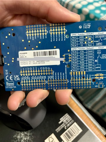
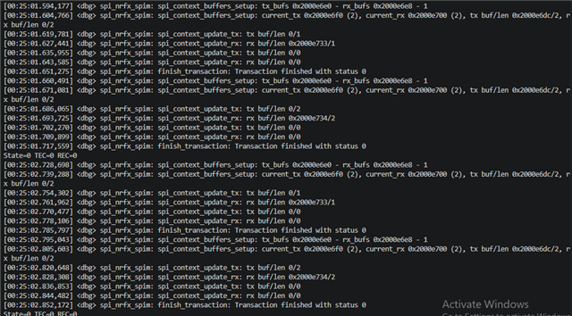
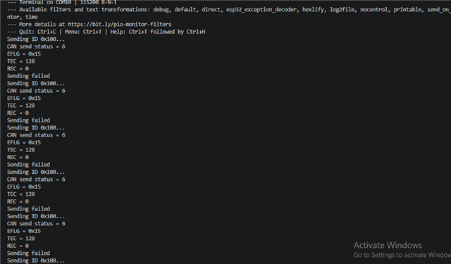
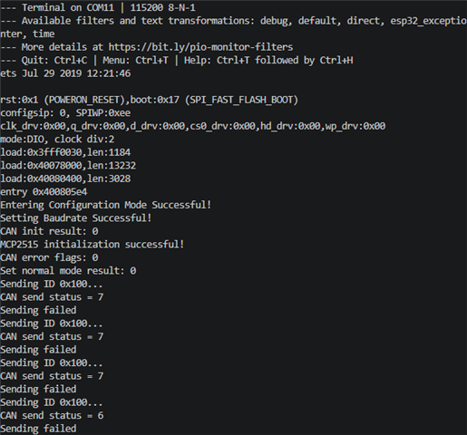
can anyone help me with this situations that i'm facing from a 1 month so i'm connecting esp32 controller to seengreat RS485 Dual CAN Bus moduler and the other hand i'm connecting nrf9160 to seengreat RS485 Dual CAN Bus moduler but i can't send or receive any messages through this and i attach the both screenshot from nrf serial terminal and from esp32 controller terminal and also i attach my overlay code and my both project files. i tried with 125,250,500 KBPS bus speed but i didn't make it and this can bus moduler have 16MHZ and it has 120 ohm resister attached with the moduler and i tried spi-max-frequency = <125000>,<250000>, <500000>, <1000000>.WACS (2).zipWACS_esp32 (2).zip

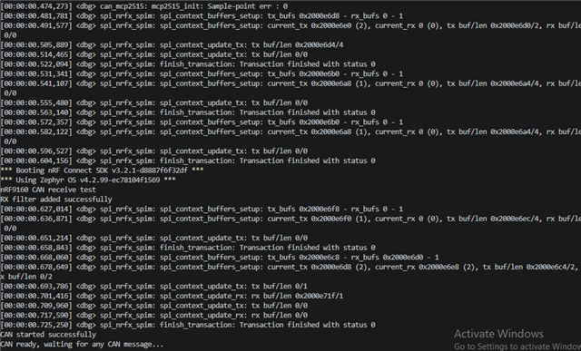
here is my overlay file code

// can mcp2515 drivers overlay

&pinctrl {
    spi3_default: spi3_default {
        group1 {
            psels = <NRF_PSEL(SPIM_SCK, 0, 13)>,
                    <NRF_PSEL(SPIM_MOSI, 0, 11)>,
                    <NRF_PSEL(SPIM_MISO, 0, 12)>;
        };
    };

    spi3_sleep: spi3_sleep {
    group1 {
        psels = <NRF_PSEL(SPIM_SCK, 0, 13)>,
                <NRF_PSEL(SPIM_MOSI, 0, 11)>,
                <NRF_PSEL(SPIM_MISO, 0, 12)>;
            low-power-enable;
        };
    };
};

/ {
    chosen {
        zephyr,canbus = &mcp2515;
    };
};

&spi3 {
    compatible = "nordic,nrf-spim";
    status = "okay";

    pinctrl-0 = <&spi3_default>;
    pinctrl-1 = <&spi3_sleep>;
    pinctrl-names = "default", "sleep";

    cs-gpios = <&gpio0 25 GPIO_ACTIVE_LOW>;

    mcp2515: can@0 {
        compatible = "microchip,mcp2515";
        reg = <0>;
        spi-max-frequency = <250000>;

        int-gpios = <&gpio0 17 GPIO_ACTIVE_LOW>;
        osc-freq = <16000000>;
        bus-speed = <250000>;
        status = "okay";
    };
};

// UART overlay
&uart2 {
    status = "okay";
    current-speed = <115200>;
};


i spend too much time on this and still didn't get anything from this so please help me to get through with this and what else i can do for debugging cuz i change the wires many times and now i order new can bus moduler to get confirmation about that is the moduler don't have the problem or what, i don't know

thanks 
vivek

Parents
  • Hello Vivek,

    Please verify if the IO voltage used by both the esp and nrf is supported by the module. Note that the nRF9160 DK is configured to use 1.8v by default, which is too low.

    Best regards,

    Vidar

  • Hi Vidar,

    i measured PO. 25(CS) = 1.80v and PO. 17(INT) = 2.58v in nRF9160DK and i measured PO.5(CS) = 3.30v and PO.4(INT) = 3.30v in esp32. so you tell me that the nRF9160 DK is configured to use 1.8v by default, which is too low then can you please tell me, what's the solution for this to send and receive the data with this model.

    thanks 

    vivek

  • Hi Vivek,

    I looked at the specification for the CAN module and saw that it required a min. voltage of 3.3v. The VDD IO configuration DK is covered in the nRF9160 DK User Guide here: https://docs.nordicsemi.com/r/bundle/ug_nrf9160_dk/page/ug/nrf91_dk/hw_description/power_sources_vdd.html. From this you can see that you will either need an external VDD IO supply to reach 3.3v, or use an external level shifter to communicate with the module. It is also important that you carefully review the specification for the module you are using to see if there may be other issue apart from the incompatible voltage level.

  • Hi vidar,

    can you tell me that why my nRF9160DK have not a SW9 switch to control the VDD power to 3.3v from 1.8v. the nordic document said that i can control the IO power 1.8v to 3.3v from SW9 switch that is located just beside the board power switch. actually SW9 is soldered in my board so i can't control it as a switch.


    here is my board number and the pictures of the SW9 switch.


    thanks

    vivek

  • You have circled around the switch in your picture. You just need to remove the protective tape before you can switch it to the 3v position. But as stated in the linked documentation, this changes the IO voltage to 3.0v, not 3.3v as required in your case.

  • Hi vidar,

    i connected level shifter with can bus moduler and nRF9160 so my connections are like i connected HV = 3.30v and GND = GND so i measured before flash the board all HV1 to HV5 are became 3.30v and at the other side LV = nrf 1.80v and GND = GND so i measured before flash the board all LV1 to LV5 are became 1.80v and i connect the HV1 MISO CAN to LV1 MISO NRF(PO=12), HV2 MOSI CAN to LV2 MOSI NRF(PO=11), HV3 SCK CAN to LV3 SCK NRF(PO=13), HV4 CS CAN to LV4 CS NRF(PO=25), HV5 INT CAN to LV5 INT NRF(PO=17) in level shifter.

    but when i flash the nRF9160 and ESP32, i didn't get succeeded and then i measured nRF pins after flash the board and sees that MOSI and SCK pins voltage drop down to 0.01 so what's that mean and please tell me that what should i have to do to get successful in this.

    thanks

Reply
  • Hi vidar,

    i connected level shifter with can bus moduler and nRF9160 so my connections are like i connected HV = 3.30v and GND = GND so i measured before flash the board all HV1 to HV5 are became 3.30v and at the other side LV = nrf 1.80v and GND = GND so i measured before flash the board all LV1 to LV5 are became 1.80v and i connect the HV1 MISO CAN to LV1 MISO NRF(PO=12), HV2 MOSI CAN to LV2 MOSI NRF(PO=11), HV3 SCK CAN to LV3 SCK NRF(PO=13), HV4 CS CAN to LV4 CS NRF(PO=25), HV5 INT CAN to LV5 INT NRF(PO=17) in level shifter.

    but when i flash the nRF9160 and ESP32, i didn't get succeeded and then i measured nRF pins after flash the board and sees that MOSI and SCK pins voltage drop down to 0.01 so what's that mean and please tell me that what should i have to do to get successful in this.

    thanks

Children
No Data
Related