trying to send and receive the data through can bus moduler using with nrf9160 and esp32 controller (using SPI)

Hi,

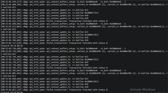
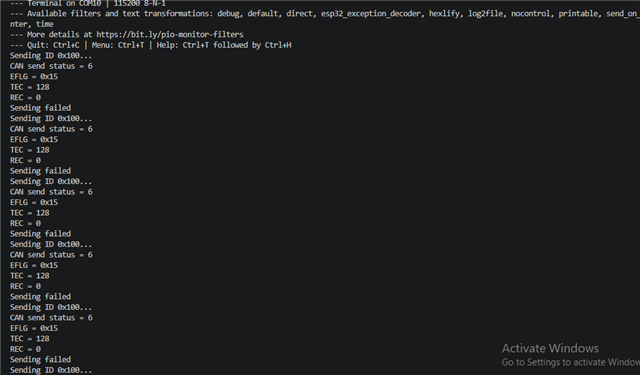
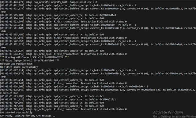
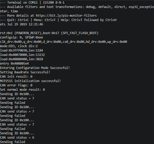
can anyone help me with this situations that i'm facing from a 1 month so i'm connecting esp32 controller to seengreat RS485 Dual CAN Bus moduler and the other hand i'm connecting nrf9160 to seengreat RS485 Dual CAN Bus moduler but i can't send or receive any messages through this and i attach the both screenshot from nrf serial terminal and from esp32 controller terminal and also i attach my overlay code and my both project files. i tried with 125,250,500 KBPS bus speed but i didn't make it and this can bus moduler have 16MHZ and it has 120 ohm resister attached with the moduler and i tried spi-max-frequency = <125000>,<250000>, <500000>, <1000000>.WACS (2).zipWACS_esp32 (2).zip
here is my overlay file code

// can mcp2515 drivers overlay

&pinctrl {
    spi3_default: spi3_default {
        group1 {
            psels = <NRF_PSEL(SPIM_SCK, 0, 13)>,
                    <NRF_PSEL(SPIM_MOSI, 0, 11)>,
                    <NRF_PSEL(SPIM_MISO, 0, 12)>;
        };
    };

    spi3_sleep: spi3_sleep {
    group1 {
        psels = <NRF_PSEL(SPIM_SCK, 0, 13)>,
                <NRF_PSEL(SPIM_MOSI, 0, 11)>,
                <NRF_PSEL(SPIM_MISO, 0, 12)>;
            low-power-enable;
        };
    };
};

/ {
    chosen {
        zephyr,canbus = &mcp2515;
    };
};

&spi3 {
    compatible = "nordic,nrf-spim";
    status = "okay";

    pinctrl-0 = <&spi3_default>;
    pinctrl-1 = <&spi3_sleep>;
    pinctrl-names = "default", "sleep";

    cs-gpios = <&gpio0 25 GPIO_ACTIVE_LOW>;

    mcp2515: can@0 {
        compatible = "microchip,mcp2515";
        reg = <0>;
        spi-max-frequency = <250000>;

        int-gpios = <&gpio0 17 GPIO_ACTIVE_LOW>;
        osc-freq = <16000000>;
        bus-speed = <250000>;
        status = "okay";
    };
};

// UART overlay
&uart2 {
    status = "okay";
    current-speed = <115200>;
};


i spend too much time on this and still didn't get anything from this so please help me to get through with this and what else i can do for debugging cuz i change the wires many times and now i order new can bus moduler to get confirmation about that is the moduler don't have the problem or what, i don't know

thanks 
vivek

  • Hi vidar,

    i connected level shifter with can bus moduler and nRF9160 so my connections are like i connected HV = 3.30v and GND = GND so i measured before flash the board all HV1 to HV5 are became 3.30v and at the other side LV = nrf 1.80v and GND = GND so i measured before flash the board all LV1 to LV5 are became 1.80v and i connect the HV1 MISO CAN to LV1 MISO NRF(PO=12), HV2 MOSI CAN to LV2 MOSI NRF(PO=11), HV3 SCK CAN to LV3 SCK NRF(PO=13), HV4 CS CAN to LV4 CS NRF(PO=25), HV5 INT CAN to LV5 INT NRF(PO=17) in level shifter.

    but when i flash the nRF9160 and ESP32, i didn't get succeeded and then i measured nRF pins after flash the board and sees that MOSI and SCK pins voltage drop down to 0.01 so what's that mean and please tell me that what should i have to do to get successful in this.

    thanks

  • Hi vidar,

    sorry to bother you but one thing i notice in my project file/ main.c, i didn't use zephyr/drivers/can_mcp2515.h and can_mcp2515.c so do i need to compile those files into main.c or do i need to use other files to use for this concept?

    thanks

  • These driver files are already included in your build when you have the mcp2515 node with the "microchip,mcp2515" binding included in your devicetree. Your application should only need to work with the top level Zephyr CAN driver API as demonstrated by the sample code. Instead of changing the code, I would recommend you try to debug the existing sample code and find out what the errors from the log indicate.

  • i have verified one more time that both mcp2515 modules use 16 MHz crystals, both use SN65HVD230 transceivers, CANH/CANH, CANL/CANL, common ground, 60 ohm measured between CANH and CANL with power off, zephyr reports CAN started successfully with State=0 TEC=0 REC=0, the esp32 MCP2515 initializes successfully but reaches TEC=128, EFLG=0x15 while REC=0.

    does this pattern suggest that the nRF9160 MCP2515 is not acknowledging frames despite being in normal mode or would you recommend checking additional MCP2515 registers or the INT handling in the Zephyr sample?

    here is screenshot of the output from both nrf and the esp32.

  • Hi Vivek,

    Thanks for the detailed measurements, Vidar is not available so I am taking up your case.

    Your ESP32 shows TEC=128 (TXEP), which just means it's sending but never getting an acknowledgement back. Your nRF9160 shows REC=0 and no received frames, meaning it's not hearing anything on the bus at all. If the nRF were actually receiving your messages but not acknowledging them, I'd expect its REC counter to climb or at least a received frame to show up, but both stay flat. So I think this isn't a "normal mode / not acknowledging" issue, and it's not the Zephyr interrupt handling or the MCP2515 registers. The frames just aren't reaching the nRF's CAN chip. I believe that usually means the problem is on the hardware side, not the code.

    One thing worth knowing is the 60 Ω you measured only confirms the two termination resistors are connected, it doesn't confirm the nRF's CAN transceiver is actually powered. A transceiver with no power still reads 60 Ω.

    Could you check a couple of things for me:

    - Measure the VCC (power) pin of the CAN module on the nRF side, it should be 3.0-3.6 V.
    - With a scope or meter, watch CANH and CANL while the ESP32 is sending, you should see them move. If they stay flat, the signal isn't getting onto the bus.
    - If possible, run the ESP32's MCP2515 in loopback mode to confirm that board is fine on its own.

    Once we know the transceiver is properly powered and the bus lines are actually moving, the sample code should work. Send over what you find and we'll take the next step from there.

    Best regards,
    Syed Maysum

Related