nRF54L15 LFRC calibration current consumption during System ON low-power mode

Hi Nordic team,

I am working on a custom board based on the nRF54L15 using nRF Connect SDK v3.1.0.

On our hardware, the nRF54L15 has a 32 MHz crystal connected to XC1/XC2, but there is no external 32.768 kHz crystal connected to XL1/XL2. The XL1/XL2 pins are used as GPIO/SPI pins for another device. Therefore, the LFCLK source is configured as the internal RC oscillator:

CONFIG_CLOCK_CONTROL_NRF_K32SRC_RC=y
CONFIG_CLOCK_CONTROL_NRF_K32SRC_RC_CALIBRATION=y
CONFIG_CLOCK_CONTROL_NRF_CALIBRATION_LF_ALWAYS_ON=y
CONFIG_CLOCK_CONTROL_NRF_CALIBRATION_PERIOD=4000
CONFIG_CLOCK_CONTROL_NRF_CALIBRATION_MAX_SKIP=1
CONFIG_CLOCK_CONTROL_NRF_CALIBRATION_TEMP_DIFF=2
CONFIG_CLOCK_CONTROL_NRF_K32SRC_250PPM=y

We are measuring current consumption in an application-level shipping mode / System ON low-power mode. In this mode, most peripherals are disabled or suspended, and the long-term average current is around several tens of microamps. However, we observe periodic current peaks. In some measurements, the peak current is around 600 µA, and in other measurements it can occasionally reach about 1 mA to 1.3 mA.

The interval of the major current peaks is approximately 8 seconds. This seems to match the LFRC calibration behavior, since our configuration uses:

CONFIG_CLOCK_CONTROL_NRF_CALIBRATION_PERIOD=4000
CONFIG_CLOCK_CONTROL_NRF_CALIBRATION_MAX_SKIP=1

We also tried changing CONFIG_CLOCK_CONTROL_NRF_CALIBRATION_PERIOD as an experiment, and the interval of the current peaks changed accordingly. Therefore, we suspect that these periodic current peaks are related to LFRC calibration.

I also understand from the nRF54L15 Product Specification that the calibrated LFRC accuracy of ±250 ppm requires calibration at least every 8 seconds. In addition, disabling CONFIG_CLOCK_CONTROL_NRF_K32SRC_RC_CALIBRATION is not an option for our BLE-enabled firmware, because MPSL requires RC clock calibration to be enabled when RC is used as the LFCLK source.

My questions are:

  1. Is it expected that LFRC calibration on nRF54L15 can cause periodic system-level current peaks in the range of several hundred microamps to around 1 mA?
  2. Does Nordic provide any measurement data or characterization data for the current consumption or energy impact of LFRC calibration on nRF54L15?
  3. Should this current peak be interpreted as the overall SoC activity during calibration, such as CPU wake-up, temperature measurement, and using the HF crystal oscillator as the calibration reference, rather than the current consumption of the LFRC oscillator block alone?
  4. For a BLE/MPSL-enabled application using LFRC as the LFCLK source, is it recommended to keep the default calibration settings instead of increasing the calibration period?
  5. If the product requires lower current in an application-level System ON shipping mode, is the recommended hardware solution to add an external 32.768 kHz crystal on XL1/XL2 and use LFXO instead of LFRC?

Thank you for your support.

I also attached three screenshots from our power measurement.

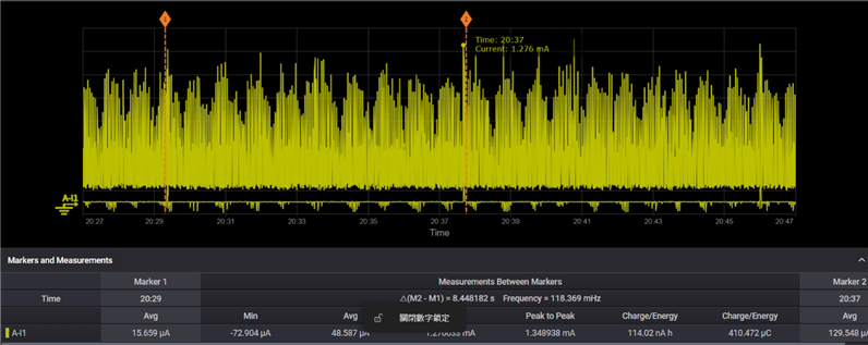
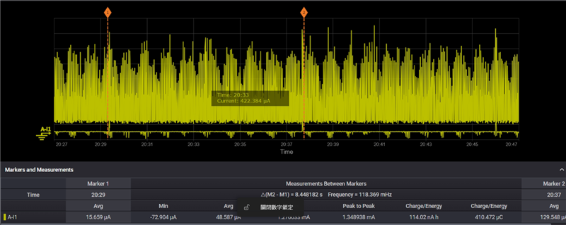
In the first screenshot, the marker interval is approximately 8 seconds, showing that the higher current event occurs periodically.

In the second screenshot, one of the peak points reaches approximately 1.276 mA.

In the third screenshot, the waveform shows that the instantaneous current samples are often between about 100 µA and 1 mA during the displayed interval. However, the average current between the markers remains around 48–49 µA. Therefore, the 1 mA to 1.3 mA values should be considered short current peaks rather than the average current consumption.

Parents
  • Hi

    1. Yes, the RC oscillator calibration calibrates towards the HF clock on the board, so these 600µA peaks would be expected during calibration. The calibration process is described here in the datasheet: https://docs.nordicsemi.com/r/bundle/ps_nrf54l15/page/clock.html-calibrating_32768khz_rcosc 

    2. The datasheet does not have any data describing the LFRC impact on current consumption, but you can use the Online Power Profiler for BLE to get estimates on the expected idle current consumption with and without a LFXO clock.  Online Power Profiler for Bluetooth LE 

    3. This would be the current consumption of the whole SoC, but you would avoid them with an external LF oscillator. In total, the full clock calibration current addition should be approximately 0.5µA to the overall idle current.

    4. Yes, for any application using BLE, you should not edit the LFRC calibration interval, as it needs to be within the BLE specification's accuracy. And for that, calibration every 4 seconds is required.

    5. An LFXO would lower the idle current consumption somewhat, but is there a reason you need to have it in system ON mode? A power management IC would be way more efficient for handling a shipping mode, but it depends on how you get it out of shipping mode I guess.

    If the average current consumption is around 40µA that is not just the LFRC oscillator's current consumption though, as it still should be in the single digit µA if the calibration is the only thing consuming current? I see you say most of the peripherals are disabled, but are anything left enabled on your end that might explain the current consumption you're seeing? Do you have a target current consumption number to reach? What is the floor current of current consumption trace here? Can you upload the whole file so we can review it for you?

    Best regards,

    Simon

  • Hi ,

    Thank you for the clarification.

    Regarding your questions:

    Yes, we agree that the average current around 40–50 µA cannot be explained by LFRC calibration alone. In our measurement, the current floor / baseline is approximately 40–50 µA, while the periodic peaks can reach several hundred µA and sometimes around 1 mA.

    Our target is to reduce the System ON low-power current as much as possible. Ideally, we would like to get closer to the single-digit µA range if possible, but we understand that this depends on what remains enabled in the system.

    At this stage, we are still checking possible board-level and firmware-level contributors, including GPIO states, possible back-powering through GPIOs connected to unpowered peripherals, external peripheral power rails, pull-up / pull-down current paths, UART or logging interfaces, sensors, PMIC states, and load switch states.

    There are external Wi-Fi and GNSS devices on the board, but during this test they are intended to be placed in sleep or low-power state. We are still verifying whether their power rails, control pins, and related GPIO states are fully consistent with the expected low-power condition, and whether there could be any remaining leakage or back-powering path.

    We do have a deeper PMIC-controlled off/shipping state available, which gives significantly lower current. However, for this specific test, we are evaluating the current consumption while the SoC remains in System ON low-power mode.

    I also checked the Online Power Profiler for Bluetooth LE with nRF54L15 and LF clock set to Internal RC. The result shows that the LF clock calibration current contribution is approximately 0.5 µA. Therefore, I understand that the LFRC calibration itself should not be the main reason for the 40–50 µA baseline current.

    I would also like to confirm one more point about the RC calibration period. My understanding is that the RC calibration period defines how often the LFRC calibration is performed. During the actual calibration activity, we can expect a current peak because the LFRC is calibrated against the HF clock. However, between two calibration events, while the system is waiting for the next calibration period, is there still any additional current consumption caused by the calibration mechanism itself, or is the average contribution mainly from the short calibration events?

    Best regards,
    Mike

Reply
  • Hi ,

    Thank you for the clarification.

    Regarding your questions:

    Yes, we agree that the average current around 40–50 µA cannot be explained by LFRC calibration alone. In our measurement, the current floor / baseline is approximately 40–50 µA, while the periodic peaks can reach several hundred µA and sometimes around 1 mA.

    Our target is to reduce the System ON low-power current as much as possible. Ideally, we would like to get closer to the single-digit µA range if possible, but we understand that this depends on what remains enabled in the system.

    At this stage, we are still checking possible board-level and firmware-level contributors, including GPIO states, possible back-powering through GPIOs connected to unpowered peripherals, external peripheral power rails, pull-up / pull-down current paths, UART or logging interfaces, sensors, PMIC states, and load switch states.

    There are external Wi-Fi and GNSS devices on the board, but during this test they are intended to be placed in sleep or low-power state. We are still verifying whether their power rails, control pins, and related GPIO states are fully consistent with the expected low-power condition, and whether there could be any remaining leakage or back-powering path.

    We do have a deeper PMIC-controlled off/shipping state available, which gives significantly lower current. However, for this specific test, we are evaluating the current consumption while the SoC remains in System ON low-power mode.

    I also checked the Online Power Profiler for Bluetooth LE with nRF54L15 and LF clock set to Internal RC. The result shows that the LF clock calibration current contribution is approximately 0.5 µA. Therefore, I understand that the LFRC calibration itself should not be the main reason for the 40–50 µA baseline current.

    I would also like to confirm one more point about the RC calibration period. My understanding is that the RC calibration period defines how often the LFRC calibration is performed. During the actual calibration activity, we can expect a current peak because the LFRC is calibrated against the HF clock. However, between two calibration events, while the system is waiting for the next calibration period, is there still any additional current consumption caused by the calibration mechanism itself, or is the average contribution mainly from the short calibration events?

    Best regards,
    Mike

Children
No Data
Related