

Hi,All:
I have a customized nRF52840 board with an external NOR Flash (W25Q64FV), and I have some confusion when conducting read and write data testing.
This is my device tree configuration:
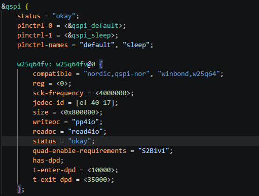
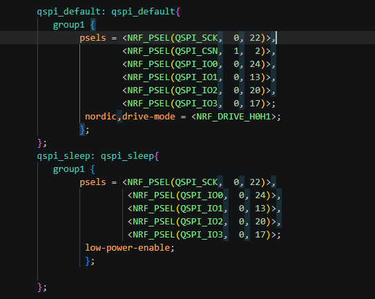
This is my test code:
void flash_stress_test(void){

    if (!device_is_ready(flash_dev))
    {
        printk("QSPI Flash initialization failed. Please check the device tree pins\n");
        return;
    }

    uint8_t write_buf[BUF_SIZE] = {0};
    uint8_t read_buf[BUF_SIZE] = {0};
    int ret;
    uint32_t loop_cnt = 0;

    printk("==== Start Flash stability testing ====\n");
    if (TEST_LOOP_COUNT > 0)
    {
        printk("Preset total number of cycles: %d\n", TEST_LOOP_COUNT);
    }
    else
    {
        printk("Infinite loop mode, power off and stop\n");
    }
    while (1)
    {
        loop_cnt++;
        printk("\n---------- The %u round of testing ----------\n", loop_cnt);
        sys_rand_get(write_buf, BUF_SIZE);
        printk("Generate random numbers:");
        for(int i=0;i<BUF_SIZE;i++){
            printk("0x%02X ", write_buf[i]);
        }
        printk("\n");

        ret = flash_erase(flash_dev, TEST_OFFSET, 4096U);
        if (ret != 0)
        {
            printk("【Error】Sector erase failed, err=%d Loop: %u\n", ret, loop_cnt);
            while (1) k_sleep(K_SECONDS(1));
        }
        ret = flash_write(flash_dev, TEST_OFFSET, write_buf, BUF_SIZE);

        if (ret != 0)
        {
            printk("【Error】Data write failed, err=%d Loop:%u\n", ret, loop_cnt);
            while (1) k_sleep(K_SECONDS(1));
        }
        ret = flash_read(flash_dev, TEST_OFFSET, read_buf, BUF_SIZE);
        if (ret != 0)
        {
            printk("【Error】Data read failed, err=%d Loop:%u\n", ret, loop_cnt);
            while (1) k_sleep(K_SECONDS(1));
        }
        printk("read data:");
        for (int i = 0; i < BUF_SIZE; i++)
        {
            printk("0x%02X ", read_buf[i]);
        }
        printk("\n");
        if (memcmp(write_buf, read_buf, BUF_SIZE) != 0)
        {
            printk("【Error】Read and write data mismatch! Loop:%u\n", loop_cnt);
            printk("Written data");
            for (int i = 0; i < BUF_SIZE; i++)
            {
                printk("0x%02X ", write_buf[i]);
            }
            printk("\n");

            while (1) {printk("Ddddd\n");k_sleep(K_SECONDS(1));}
        }
        printk("This round of verification has passed");
        if (TEST_LOOP_COUNT != 0 && loop_cnt >= TEST_LOOP_COUNT)
        { break;   }
        k_sleep(K_MSEC(5));
    }
    printk("\n===== All %u round pressure tests passed,  =====\n", loop_cnt);
}
Then add to the device tree:
writeoc = “pp4io”;
readoc = “read4io”;
When Quad SPI is enabled, all data outputs are 0xFF, as shown in the figure
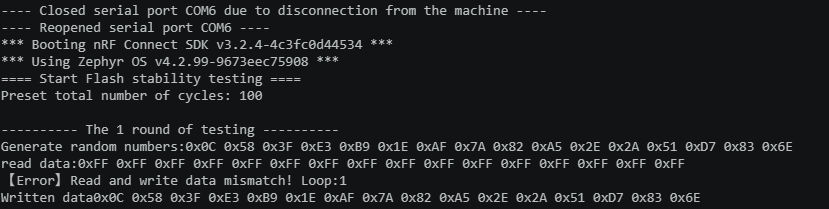
fter annotation, all read and write data are normal.
I think it is: Four link activation requirement="S2B1v1"; Not working (QE) or
other reasons.Also, can you give me some suggestions on whether my device tree
configuration is normal and whether there are any issues with the code
Thanks


