This post is older than 2 years and might not be relevant anymore
More Info: Consider searching for newer posts

[NRF51822CEAA][CUSTOM BOARD]- Help in debugging custom board

Hi,

I have made a custom board using NRF51822CEAA, following the reference design. Some modules are working properly. But I'm facing following issues on some boards.

  1. When I connect the debugger from PCA10028 to program the board and use Jlink to connect, PCA10028 disconnects from PC and then reconnects. This way I'm unable to program some boards. I have checked the connections and everything is fine as the same setup works for some other boards. The error message shown while trying to connect is :

    ****** Error: Communication timed out: Requested 20 bytes, received 0 bytes ! Could not read hardware status! Can not connect to target.

  2. On some boards, I'm able to program everything but the device isn't advertising. However I'm able to use debugger and RTT is also printing. So my guess is application is running at least. Also the same program is working for the boards that are working properly.

Please help in debugging these issue.

Regards

Lalit Kumar


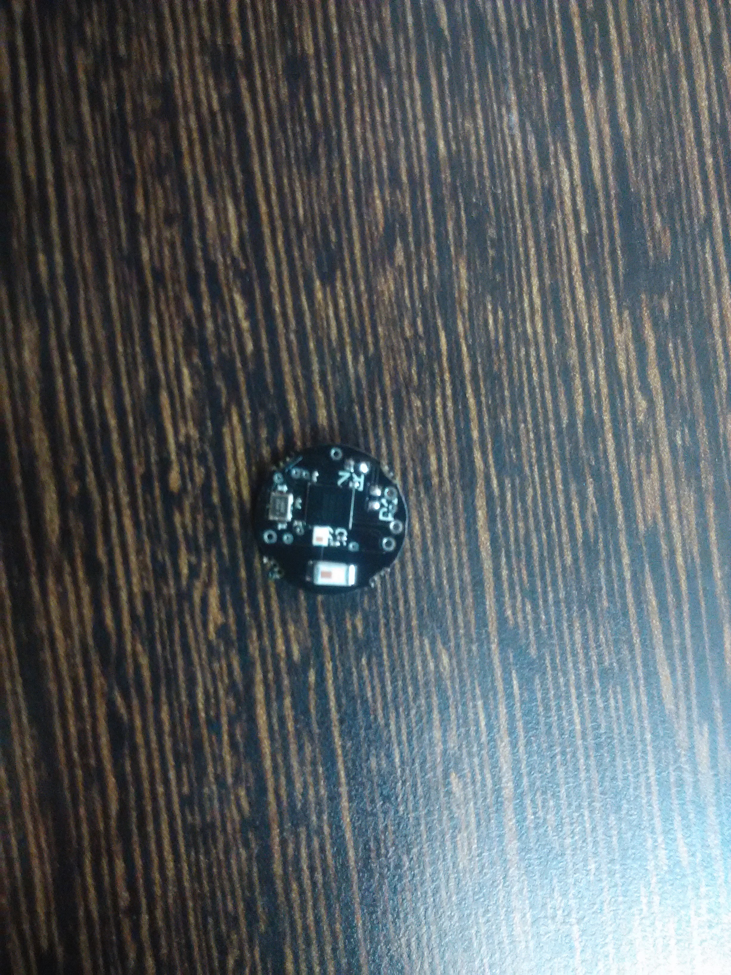
EDIT: I'm attaching the schematic as layout and layout as gerber files as well as EAGLE Files. the module is very small, so a good picture of it is difficult. If it is absolutely required, I'll try something. transmitter_side_sch.pdf

transmitter_side_gerber.zip

transmitter_side_eagle.zip


EDIT:

If by setup you mean the PCB, here is an image of the same. Sorry can't do better than that. If you mean connections, then I'm following the this guide.

transmitter

Parents
  • FormerMember
    0 FormerMember

    Could you please upload a schematic, layout, and a picture of the module? The problem may be related to the schematic/layout.

Reply
  • FormerMember
    0 FormerMember

    Could you please upload a schematic, layout, and a picture of the module? The problem may be related to the schematic/layout.

Children
  • I have edited the question and attached the files.

  • FormerMember
    0 FormerMember in reply to FormerMember

    Thanks! Could you also upload a picture of the setup?

  • I have uploaded the same. Sorry can't take a better picture as the size is too small to focus properly. Also I would like to mention again, just in case, that some PCBs of the same design are working perfectly.

  • FormerMember
    0 FormerMember in reply to FormerMember

    Thanks! Okay, I see. On the boards that doesn't work/run code, could you verify if the 16 MHz crystal has been mounted correctly, i.e. not shifted by 90 degrees for instance ?

    If you run you chip in debug mode, where does the problem occur?

  • I'll explain in detail what is happening. I have 12 board, soldered by pick and place. I am using nrf51-dk to program them as I have mentioned. When I connect the pins to program the board and try to connect it using JLinkExe on Linux, I am able to connect 8 out of 12. For the rest 4, the dk just disconnects from pc and reconnects. On working 8, i upload a BLE example and softdevice from sdk11. 4 are working properly and broadcasting well. On the remaining 4 out of initial 8, I'm able to see the output on RTT and run app without sd, but they are not broadcasting for app with sd. Sorry for the mess here, don't know a better way to explain :P