This post is older than 2 years and might not be relevant anymore
More Info: Consider searching for newer posts

How much current consumption when we use internal 32k RC ?

I use the nRF52832 IC of WLCSP package. In addition, it sets as follows:

                            {.source        = NRF_CLOCK_LF_SRC_RC,            \
                             .rc_ctiv       = 16,                                \
                             .rc_temp_ctiv  = 2,                                \
                             .xtal_accuracy = NRF_CLOCK_LF_XTAL_ACCURACY_250_PPM}

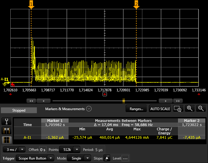
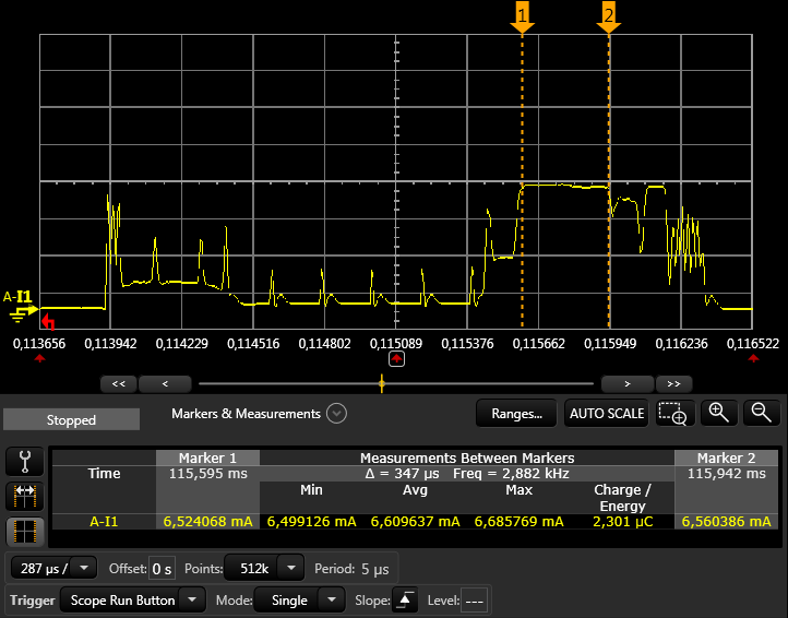
How much current consumption increases as compared with the case of using an external crystal ?

Also, please tell us in detail why the current consumption increases.

thank you

uba

Parents
  • There are 3 factors that will affect the current consumption

    1. LFRC vs LFXO run current
    2. LFRC calibration
    3. Window widening in connection

    1. Run current

    The numbers for the different run currents can be found in the product specification.

    • RC: 0.6 µA
    • XO: 0.25 µA

    This means that the average run current will increase with 0.35µA


    2. Calibration

    In order to achieve a 250 ppm clock accuracy for BLE (which is required by the BLE spec), the LFRC clock must be calibrated at least every 8 seconds and every 4 seconds when the temperature changes more than 0.5 degrees (.ctiv=16, .temp_ctiv=2). See the SD spec for more info on this.

    The LFXO does not need to be calibrated.

    The calibration takes about 17ms and consumes 460µA in average during this time period. This results in a charge of:

    17ms * 0.460mA = 7.82µC
    

    A calibration interval of 8 seconds gives the average current consumption:

    7.82µC / 8s = 0.98µA
    

    Here is a plot of the calibration event: Calibration

    For non BLE applications the calibration might not be critical and you could use longer intervals.


    3. Window widening

    Window widening (will call it WW from now) is the increase of the time the RX has to listen in order to not miss the packet to receive. This is only relevant in peripheral connection mode, not in advertising mode. The peripheral listens from WW before the expected receive point in time, until WW after the expected point. This means that the time the RX is listening will increase by WW in average.

    The formula to calculate the WW is as follows (from BLE core spec v4.2, Vol 6, Part B, chapter 4.5.7)

    WW = ((masterSCA + slaveSCA)/1000000) * timeSinceLastAnchor
    

    TimeSinceLastAnchor is equal to the connection interval (no slave latency), the time since the clocks were last synced. masterSCA and slaveSCA is the sleep clock accuracy for master and slave, or if you want, the ppm accuracy you specify in code.

    So if you have a 250ppm SCA (which you will have if you are using LFRC), and lets say that the central is still 20ppm, the WW will be,

    WW = 270µ * INT
    

    where INT is the connection interval in seconds. To find the current consumed (charge) during this extra WW time, we have to multiply this with the RX current.

    Q = WW * I_RX
    

    Now, since we want to find the average current with different connection intervals we can divide the charge (Q) with the interval, but since WW already is dependent on the interval (INT), this will cancel out and we get a constant average current we can add to all connection intervals.

    I_ww = Q/INT
         = 270µ * INT * I_RX / INT
         = 270µ * I_RX
    

    The I_RX is 6.6mA (see measurements below), so then we can find the average current consumed by the WW:

    I_ww = 270µ * 6.6mA = 1.78µA
    

    The 20ppm SCA when using LFXO will also have a small WW, and can be found in a similar way:

    I_ww = 40µ * 6.6mA = 0.26µA (remember to add 20ppm for both master and slave = 40ppm)
    

    The increased average current when using LFRC instead of LFXO will then be,

    1.78µA - 0.26µA = 1.52µA
    

    Here is a plot of the connection event with 250ppm slave SCA + 20ppm master SCA and a one second connection interval. We have 270µs WW and 80µs receive time = 350µs (80µs, because an empty packet consists of 80 bits, and it is transmitted at 1Mb/s)

    RX


    To sum up, the increased average current will be a sum of the 3 above factors

    1. 0.35µA
    2. 0.98µA
    3. 1.52µA

    Since all of the above average currents are independent of connection interval, you can add this as a constant for all connection intervals:

    0.35 + 0.98 + 1.52 = 2.85µA
    

    And for advertising, when WW is not relevant, we get:

    0.35 + 0.98 = 1.33µA
    

    So to finally answer your question. The expected increase in current during connection when using LFRC instead of LFXO is 2.85 µA. And during advertising a 1.33 µA increase in current.

  • Thank you so, so much!

    I have a question. There is a description in SDK_11.0.0, such as the following.

    @note For nRF52, the application must ensure calibration at least once every 8 seconds to ensure +/-250ppm clock stability. The recommended configuration for NRF_CLOCK_LF_SRC_RC on nRF52 is rc_ctiv=16 and rc_temp_ctiv=2. This will ensure calibration at least once every 8 seconds and for temperature changes of 0.5 degrees Celsius every 4 seconds. See the Product Specification for the nRF52 device being used for more information.*/

    Which is correct, "ctiv=16" or "ctiv=32" ?

Reply
  • Thank you so, so much!

    I have a question. There is a description in SDK_11.0.0, such as the following.

    @note For nRF52, the application must ensure calibration at least once every 8 seconds to ensure +/-250ppm clock stability. The recommended configuration for NRF_CLOCK_LF_SRC_RC on nRF52 is rc_ctiv=16 and rc_temp_ctiv=2. This will ensure calibration at least once every 8 seconds and for temperature changes of 0.5 degrees Celsius every 4 seconds. See the Product Specification for the nRF52 device being used for more information.*/

    Which is correct, "ctiv=16" or "ctiv=32" ?

Children
No Data
Related