This post is older than 2 years and might not be relevant anymore
More Info: Consider searching for newer posts

What is the startup time of a discrete nRF51822 module vs nRF51-DK board?

I know this is somewhat "how long is a piece of string". I'm happy for guidance rather than solid numbers:

I'm trying to spec a "keep alive" circuit for an nRF51822 project. The general principle is there is an LDO (with enable pin) that is first activated by a user pushbutton. Next, as fast as possible, the nRF51822 turns-on (now that it has power) and switches on a GPIO to keep the LDO enable pin high (therefore keeping the LDO on). This means the nRF can turn everything off by setting the enable pin to low.

To keep the enable line high during the time between the button being pressed & released, and the nRF51822 to wake-up, I'm just using a capacitor and resistor specified with the right discharge duration. So the time for RC-discharge to minimum enable-pin voltage needs to be a bit longer than the power-on time for the nRF51822.

I've looked at the product specification and especially at this related question here: devzone.nordicsemi.com/.../

I know that the practical start-up time (from power-input to GPIO-output) depends on the input voltage, I'm using 3.3V which should give pretty fast start-up (~2ms according to linked question).

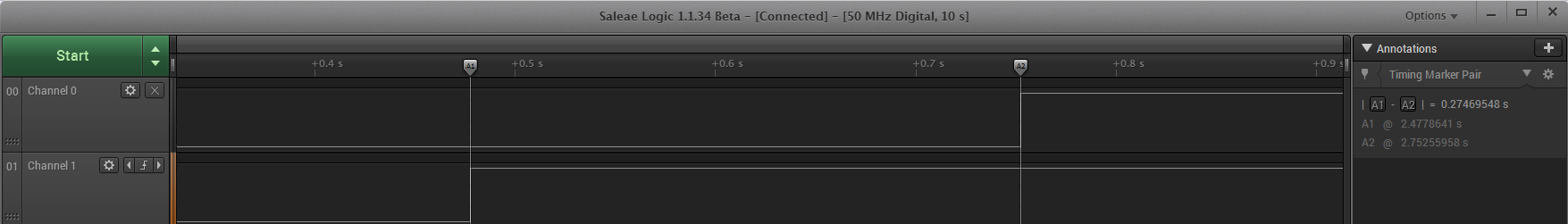
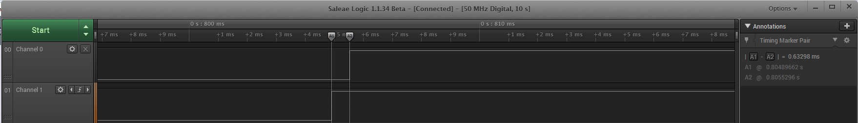
But... Using the nRF51-DK dev. board to prototype this I see with my oscilloscope that the practical start-up time is more like 350-400ms... It's dramatically larger than what I was expecting... Obviously this start-up time includes LDO start-up, but that is ~50uS according to my scope.

So, my main question(s):

  • Does the nRF51-DK take much longer to start than a raw/lone nRF51822 module?
  • Approximately what start-up times could I expect with a real nRF51822 module? (Are values in the product spec. & the related question realistic for the power-on->GPIO-on start-up time I'm describing?)

My circuit is very flexible and I can manage even these large start-up times, but reducing it to product spec. values would be very useful to avoid a big capacitor.

Sorry for the long question, lots of detail. Any help/advice is appreciated.

Parents
  • Hi,

    The startup you're seeing is the low frequency clock which has a typical startup time of 0.3s. Please see the below logic analyzer trace where channel 0 is the toggled GPIO and channel 1 is the power. First with initialization of the LF-clock. (300 ms measured)

    image description

    Then without initialization of the LF-clock. (0.8 ms measured)

    image description

    For your application you can toggle the GPIO before starting the LF-clock. Or if you have a particularly need for clocking right at the start you can use the RC clock, which has a startup time of ~400 µs, before initializing your LF crystal later.

    Best regards,

    Øyvind

  • Hi Øyvind,

    Thanks v. much for your response. I worked further on this yesterday after posting and, from reading other related questions and playing with an oscilloscope I have confirmed exactly what you said.

    Switching to the internal RC clock helped but seems to reduce start-up to ~100ms, not ~400us... But this could be due to some timeout code I'm not noticing however so I wouldn't worry about this.

    As you suggested I now toggle the GPIO before any clock setup code and a solid <1ms response seems normal! Success!

    However I now have a different issue. At ~100ms after initial response the GPIO pin drops to 0V for ~40ms (killing the LDO if I don't keep the button held).

    What could be causing this?? Anything hardware-based? Or do you think odd mbed initialisation stuff...?

    Here's a link to my scope reading: http://imgur.com/lnCCGYu Blue line is response GPIO, yellow is power.

Reply
  • Hi Øyvind,

    Thanks v. much for your response. I worked further on this yesterday after posting and, from reading other related questions and playing with an oscilloscope I have confirmed exactly what you said.

    Switching to the internal RC clock helped but seems to reduce start-up to ~100ms, not ~400us... But this could be due to some timeout code I'm not noticing however so I wouldn't worry about this.

    As you suggested I now toggle the GPIO before any clock setup code and a solid <1ms response seems normal! Success!

    However I now have a different issue. At ~100ms after initial response the GPIO pin drops to 0V for ~40ms (killing the LDO if I don't keep the button held).

    What could be causing this?? Anything hardware-based? Or do you think odd mbed initialisation stuff...?

    Here's a link to my scope reading: http://imgur.com/lnCCGYu Blue line is response GPIO, yellow is power.

Children
No Data
Related