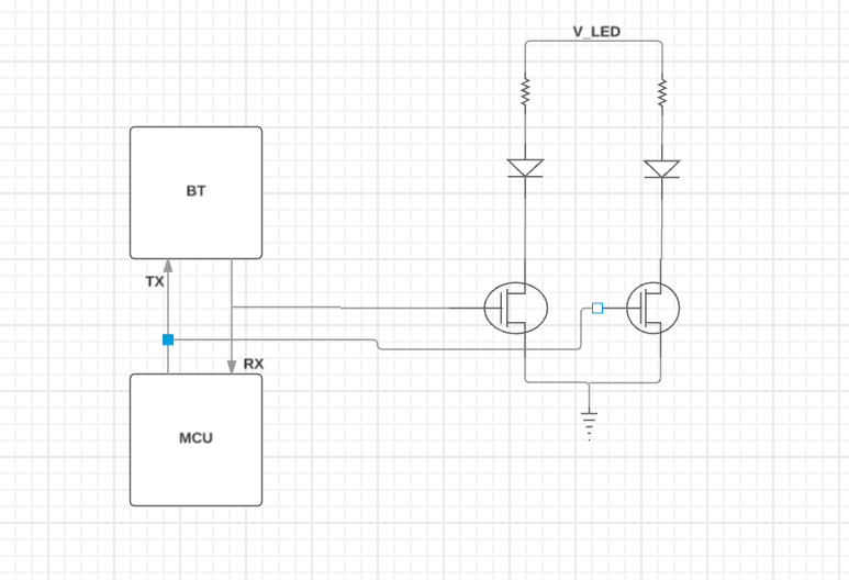
I want to know which pins serve the purpose of TX and RX in nRF51822. I suspect its the ANT1 and ANT2 but i want to confirm and also if the following would be a good way to place status LEDs on the TX and RX lines

I want to know which pins serve the purpose of TX and RX in nRF51822. I suspect its the ANT1 and ANT2 but i want to confirm and also if the following would be a good way to place status LEDs on the TX and RX lines

Hi,
It is a very bad idea to place LEDs and transistors on ANT1 and ANT2, these are differential outputs for the 2.4 GHz radio signal. Normal transistors and LEDs are not rated for anything near this frequency and will not work, actually it is very likely that they will become hot and break.
The reference design should be followed, there's also a tutorial on general PCB design guidelines.
Best regards,
Øyvind
I don't think the OP understands those are the 2.4GHz antenna outputs for some reason and thinks they are UART lines despite awneil trying to explain it.
You are completely right RK. 4 years ago I was a bit of new person in electronics and layouts. I am actually very embarrassed to read my questions and replies here. But thankfully I can understand everything the commenters have said 4 years later