
Hello everyone,
I have a program which set configurations by using write (nrf_drv_twi_tx) in the registers of a sensor. I use the SDK 8 in the nRF51.
Here is the code:
// *************************************** Temperature cfg *************************************** //
// Write cfg to reg 0x06
for(slave_address=0x76; slave_address < 0x78; slave_address++)
{
ret_code = nrf_drv_twi_tx(&p_twi_instance, slave_address, &temp_reg, 1, true);
nrf_delay_ms(200);
                ret_code = nrf_drv_twi_tx(&p_twi_instance, slave_address, temp, sizeof(temp), false);
nrf_delay_ms(200);
 }

// ****************************************** Pressure cfg *************************************** //
// Write cfg to reg 0x07
for(slave_address=0x76; slave_address < 0x78; slave_address++)
{
ret_code = nrf_drv_twi_tx(&p_twi_instance, slave_address, &press_reg, 1, true);
nrf_delay_ms(200);
                ret_code = nrf_drv_twi_tx(&p_twi_instance, slave_address, press, sizeof(press), false);
nrf_delay_ms(200);
 }

// ***************************************** Interrupt and FIFO ********************************** //
// Write cfg to reg 0x09
for(slave_address=0x76; slave_address < 0x78; slave_address++)
{
ret_code = nrf_drv_twi_tx(&p_twi_instance, slave_address, &interr_reg, 1, true);
nrf_delay_ms(200);
                ret_code = nrf_drv_twi_tx(&p_twi_instance, slave_address, interr, sizeof(interr), false);
nrf_delay_ms(200);
}
Could you help me to respond to those questions and solve the problem please?
-
The sensor (slave) address is 0x77. When I use it directly, I get an ERROR event. Otherwise, I have to use the “for” loop to get a TXSENT event. Could you explain me please?
-
Can functionalities of debugger be affected by the program as 2 successive writes? With the debugger I can see that until the end of the first write, everything works properly. But when I go on to the second write, it seems like the debugger no longer reacts. However, when I begin to put a breakpoint at the end of the 2nd write, the debugger answers and shows that it works well.
Maybe the 2 subjects are linked, maybe not. In any case, thank you in advance for your answers.
Hello,
Let me give more details about what I have done step by step.
-
As I said, the slave address is 0x77. At the beginning, I tried to transmit the byte 0x05 to the register 0x08 of the slave. Here is the code :
uint8_t slave_address = 0x77; uint8_t register_address = 0x08; uint8_t data = 0x05;
ret_code = nrf_drv_twi_tx(&p_twi_instance, slave_address, ®ister_address, 1, true); nrf_delay_ms(1);
ret_code = nrf_drv_twi_tx(&p_twi_instance, slave_address, &data, 1, false); nrf_delay_ms(1);
But it does not work.
Here is what I observed with the logical analyzer:
The first call to the slave delivers a NACK (non-acknoledge) at the 9th clock pulse.
- Then I noticed that there were times, passing by the slave address 0x76 solved the problem.
Here is the code :
uint8_t slave_address_0 = 0x76;
uint8_t slave_address = 0x77;
uint8_t register_address = 0x08;
uint8_t data = 0x05;
ret_code = nrf_drv_twi_tx(&p_twi_instance, slave_address_0, ®ister_address, 1, true);
nrf_delay_ms(1);
ret_code = nrf_drv_twi_tx(&p_twi_instance, slave_address_0, &data, 1, false);
nrf_delay_ms(1);
ret_code = nrf_drv_twi_tx(&p_twi_instance, slave_address, ®ister_address, 1, true);
nrf_delay_ms(1);
ret_code = nrf_drv_twi_tx(&p_twi_instance, slave_address, &data, 1, false);
nrf_delay_ms(1);
The third call to the slave delivered an ACK at the 9th clock pulse and it was directly followed by the fourth call to the slave which transmitted the register address 0x08. That seems like it is necessary to wake up the slave with the address 0x76 before calling it with the address 0x77.
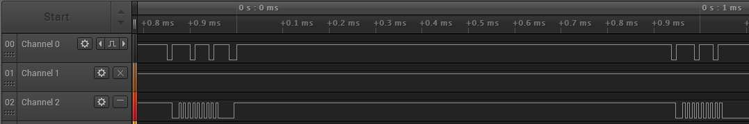
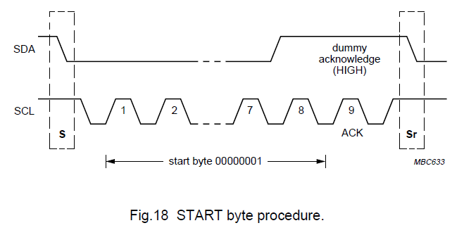
- Finally, I tried to follow the Phillips I²C bus specification using a START byte to help synchronizing those chipset.
I have succeeded to produce the same chronogram as below which is in the specification:
with this code :
uint8_t start_byte = 0x00;
uint8_t slave_address = 0x77;
uint8_t register_address = 0x08;
uint8_t data = 0x05;
ret_code = nrf_drv_twi_rx(&p_twi_instance, start_byte, &start_byte, 1, false);
nrf_delay_ms(1);
ret_code = nrf_drv_twi_tx(&p_twi_instance, slave_address, ®ister_address, 1, true);
nrf_delay_ms(1);
ret_code = nrf_drv_twi_tx(&p_twi_instance, slave_address, &data, 1, false);
nrf_delay_ms(1);
But it does not work yet, as the logical analyzer shows:
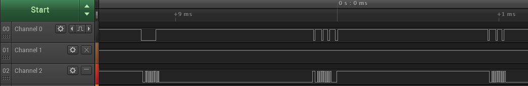
I come to you again to know if you could help me to find a solution please.
Thank you in advance, Best regards,

