This post is older than 2 years and might not be relevant anymore
More Info: Consider searching for newer posts

Review of nRF 8001 schematic with Antennae

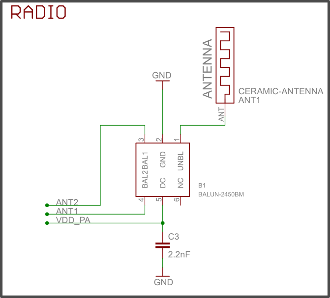
I have a schematic in which Balun is connected as a matching network to Ant1&Ant2 pins making the output impedance 50 ohms. Now i want to connect an Antennae to it which is surely of 50ohm but i have read in previous questions on the forum that tuning pi network has to be connected between the output impedance and the antennae(50 ohm). I am attaching my Schematic, review it and can you tell me what will be the values in the pi network i.e the values of L1,C8 and C15. And which antennae should i connect i.e whether PCB Antennae or another. And what will be the specification of the antennae to be connected? Review the schematics and answer the above questions. Any help is appreciated!!.

MySchematic.pdf

  • Hello, I'm interested in an answer too. RF part on my prototype (nrf51822) doesn't work. I have chosen this ballun and this ceramic antenna with a 50ohm line. I'm not RF engineer, did I forget something?

    Attached, my shematic and my layouts

    shema.png

    top (2).png

    bottom.png

  • Are you sure it will work okay with that balun? I just saw that the sheet says "Optimized for Nordic's Chipset nRF24L01, nRF24L01+, nRF24LE1, nRF24LU1, nRF24AP2, and nRF8001".

  • RF part on nrf518001 and 51822 are very similar and i've vhosen this ballun because it's bigger than the recomanded BAL-NRF02D3 but yes, maybe it was an error...

  • I personally don't know at all, just wanted to make sure you had considered it :)

  • Hardware reviews are in general better done as regular support cases, since they will often conclude with hardware being sent in for tuning.

    To answer your specific questions Manish, the values of a pi-network can't be decided beforehand, and must be determined by measuring on a prototype. This kind of measuring is something we can help with, but it requires that the design has been reviewed in a regular support case, and all our comments taken into consideration.

    Your schematic doesn't show what kind of balun you use, but in general, you need to make sure that the balun is made for exactly the chip that you're using. For the nRF8001, you can use the Johanson balun linked above for example. When using a balun it's also extremely important to follow the reference layout of the balun manufacturer exactly, and place the balun at exactly the correct distance from the chip, and making sure the grounding of the balun is as good as possible.

    As for antenna tuning components, this is dependent on the antenna type used. If you use a straight PCB antenna, it's usually sufficient to include one shunt capacitor, and making the antenna a little longer than should be needed. The antenna can then be tuned by adjusting the capacitor and the length of it.

    However, for meander, inverted F or chip antennas, it isn't really possible to tune by adjusting the length, and a full pi-network is hence recommended. This should be placed between the balun/ matching network and the antenna, exactly as you've done. You can never combine components for antenna tuning with components of the matching network or the recommended circuit for the balun, so make sure to include all 3 footprints separately. It could very well be that not all of them will actually be needed, but initially, the footprints should be put in place to allow maximum freedom when tuning.

    As mentioned, it is not possible to determine the length of the antenna or values for the shunt capacitor or pi-network without measuring on the design, which is one reason for creating a regular support case and requesting help with this.

    If you want to do tuning yourself, we do however have a whitepaper on tuning the matching network and a separate one on antenna tuning, which may be useful to refer to anyway.

Related