This post is older than 2 years and might not be relevant anymore
More Info: Consider searching for newer posts

Review of nRF 8001 schematic with Antennae

I have a schematic in which Balun is connected as a matching network to Ant1&Ant2 pins making the output impedance 50 ohms. Now i want to connect an Antennae to it which is surely of 50ohm but i have read in previous questions on the forum that tuning pi network has to be connected between the output impedance and the antennae(50 ohm). I am attaching my Schematic, review it and can you tell me what will be the values in the pi network i.e the values of L1,C8 and C15. And which antennae should i connect i.e whether PCB Antennae or another. And what will be the specification of the antennae to be connected? Review the schematics and answer the above questions. Any help is appreciated!!.

MySchematic.pdf

Parents
  • I'm know very little about RF design, but I have used a Johanson 2450BM14A0002 balun chip along with a Johanson 2450AT18A100 chip antenna for an nRF8001-based board, and the combination worked great. I didn't use any kind of additional matching network beyond the balun chip.

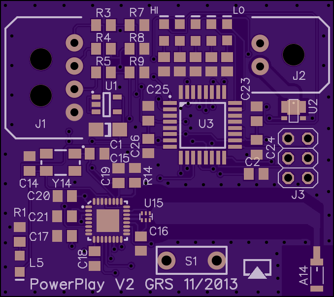
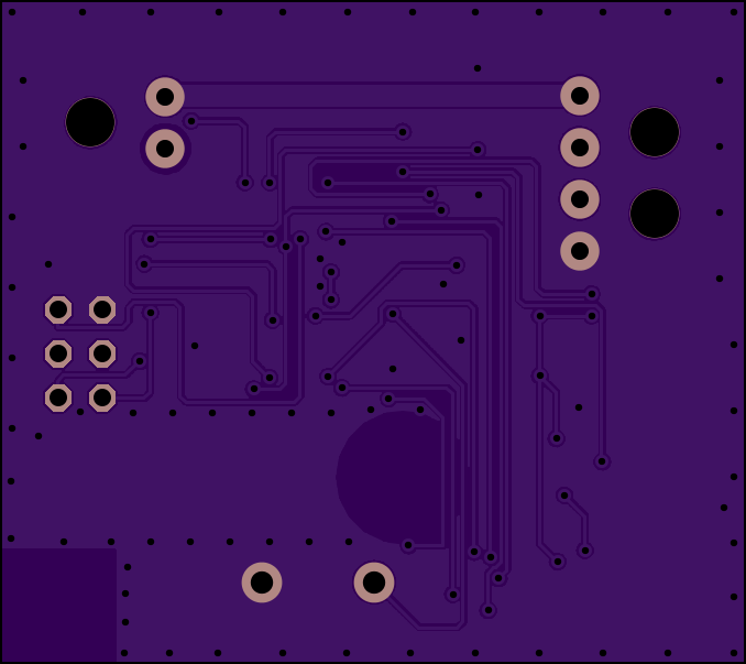
    I did, however, follow Johanson's layout suggestions pretty closely. There are a couple of different Johanson tech notes with not-entirely-consistent advice; I used page 2 of the antenna chip data sheet (which I'll attach below) as the model.

    In particular, I did ground planes on both sides of the board with frequent vias on the periphery, a wide, 19-mm stripline "runway", a large keep-out area on the ground plane behind the stripline, a circular no-ground area behind the balun itself, and no ground plane on either side in the immediate vicinity of the antenna, using the recommended margins. My total ground plane area was only about 60% of the recommendation, but there wasn't much I could do about that.

    As I said, performance was great. On the other hand, all that keep-out area is expensive; I'm not sure it's any more space-efficient than a PIFA or meander PCB antenna. Also, I'm hand-reflowing and that balun chip packs six connections into a microscopic little package. I was probably just lucky that it reflowed without any bridges.

    Johanson 2450AT18A100 Antenna.pdf

    Front.png

    Back.png

  • Excellent points, Ole. My board isn't bound for mass production, so the only concern was that it function as a BTLE device and not cause any obvious local interference. I'm not by any means recommending skipping the pi network, design review, or signal analysis for a production board.

    I was mostly responding to thomas, who was having trouble getting the antenna to work at all. According to my very limited experience, yes, you should be able to follow the cookbook recipe blindly but carefully and end up with something that at least functions as a radio with reasonable range. And there doesn't seem to be any problem pairing the nRF8001 with that Johanson balun chip.

Reply
  • Excellent points, Ole. My board isn't bound for mass production, so the only concern was that it function as a BTLE device and not cause any obvious local interference. I'm not by any means recommending skipping the pi network, design review, or signal analysis for a production board.

    I was mostly responding to thomas, who was having trouble getting the antenna to work at all. According to my very limited experience, yes, you should be able to follow the cookbook recipe blindly but carefully and end up with something that at least functions as a radio with reasonable range. And there doesn't seem to be any problem pairing the nRF8001 with that Johanson balun chip.

Children
No Data
Related