
Hello everyone,
I am currently trying to make simple exchanges with an NFC chip using SPI.
Configuration is: nRF52 on dev board 10040 with example from SDK12 located in peripheral\spi.
I am using configuration already present which is SPI0 with Easy DMA enabled. Although, I changed the PIN assignments :
#ifndef SPI_SCK_PIN
#define SPI_SCK_PIN 12
#endif

// <o> SPI_MISO_PIN - Pin number  <0-31>

#ifndef SPI_MISO_PIN
#define SPI_MISO_PIN 14
#endif

// <o> SPI_MOSI_PIN - Pin number  <0-31>

#ifndef SPI_MOSI_PIN
#define SPI_MOSI_PIN 13
#endif

// <o> SPI_SS_PIN - Pin number  <0-31>

#ifndef SPI_SS_PIN
#define SPI_SS_PIN 15
#endif
Here follows my SPI configuration:
nrf_drv_spi_config_t spi_config = NRF_DRV_SPI_DEFAULT_CONFIG;
spi_config.ss_pin   = SPI_SS_PIN;
spi_config.miso_pin = SPI_MISO_PIN;
spi_config.mosi_pin = SPI_MOSI_PIN;
spi_config.sck_pin  = SPI_SCK_PIN;
spi_config.mode = NRF_DRV_SPI_MODE_1;
spi_config.frequency = NRF_DRV_SPI_FREQ_125K;
APP_ERROR_CHECK(nrf_drv_spi_init(&spi, &spi_config, spi_event_handler));
I am trying to read a bunch of registers values by sending 2 bytes (one for the command and one for the register number) and receive 4 bytes as a response. So main loop is looking like that:
uint8_t block = 0x00;
static uint8_t       m_tx_buf[] = {0x7f, 0x02, 0,0,0,0};           /**< TX buffer. */
static uint8_t       m_rx_buf[7];    /**< RX buffer. */
static const uint8_t m_length = sizeof(m_tx_buf);        /**< Transfer length. */
while (1)
    {
        // Reset rx buffer and transfer done flag
        memset(m_rx_buf, 0x55, m_length);
        spi_xfer_done = false;
        m_tx_buf[1] = block;

        APP_ERROR_CHECK(nrf_drv_spi_transfer(&spi, m_tx_buf, m_length, m_rx_buf, 6));
        NRF_LOG_DEBUG("Received :");
        NRF_LOG_HEXDUMP_DEBUG(m_rx_buf, 6);

        while (!spi_xfer_done)
        {
            __WFE();
        }
        block += 2;
        block %= 16;
        NRF_LOG_FLUSH();

        LEDS_INVERT(BSP_LED_0_MASK);
        nrf_delay_ms(200);
    }
I filled the reception buffer with 0x55 on purpose to be sure that I am not reading some 0x00 by mistake or misinterpretation of the MISO line. And by the following RTT log I can confirm that no data has been written in the rx buffer after SPI transaction:
SPI:DEBUG:Tx data:
SPI:DEBUG:
7F 00 00 00 00 00                                ......
SPI:DEBUG:Disabling list for RX
APP:DEBUG:Received :APP:DEBUG:
55 55 55 55 55 55                                UUUUUU
APP:INFO:Transfer completed.
SPI:INFO:Transfer tx_len:6, rx_len:6
SPI:DEBUG:Tx data:
SPI:DEBUG:
7F 02 00 00 00 00                                ......
SPI:DEBUG:Disabling list for RX
APP:DEBUG:Received :APP:DEBUG:
55 55 55 55 55 55                                UUUUUU
However, if I trace what happens indeed on the lines, I see the response :
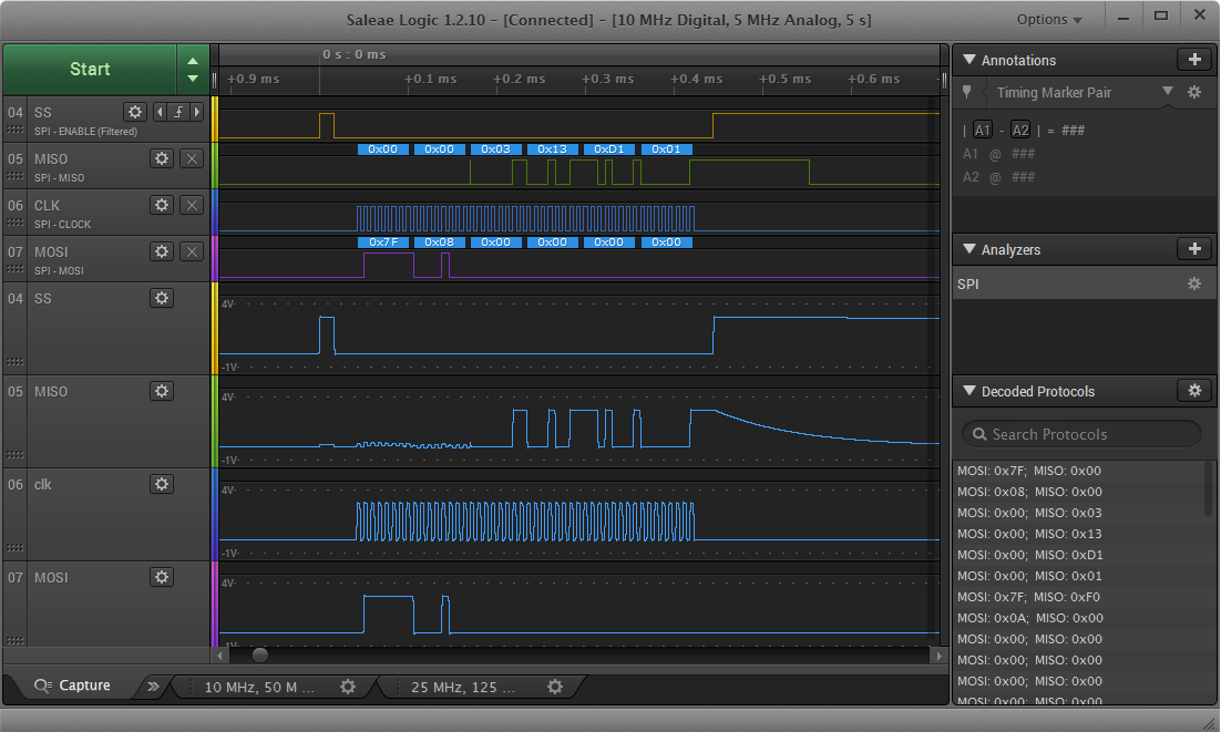
I cannot find what I did wrong. The LIST is not enabled but I don't see the point as I only have few bytes to exchange. I was not able to find where this RX buffer is supposed to be filled.
I tried different frequencies from 1M to 125K, nothing is changing. I tried the blocking mode by not providing the handler during the init, no better result. I tried to change SPI instance to 2 to be inline with PIN definitions... nothing helps...
What can I do to find my error?
Thank you for your help
