This post is older than 2 years and might not be relevant anymore
More Info: Consider searching for newer posts

How to read register from ADXL362 via SPI

Hi,

I have written a short driver for the ADXL362 accelerometer, which I'm attaching here, and I've connected breakout board of the accelerometer from Sparkfun to the nRF51 DK as specified in the picture from the datasheet. I also connected the accelerometer's GND and V+ to the DK's GND and VDD respectively.
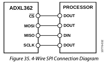
here

In my application, I'm using the driver to read a register in the accelerometer (DEVID_AD in address 0x00) that I understand should always come back with the constant value of 0xAD. However, when debugging the application in Eclipse, the receive buffer is always 0x00.

I'm setting the SPI driver to use mode 0 since the accelerometer's datasheet says it is CPOL = CPHA = 0.

Could any body point out anything I might be doing wrong? The datasheet also says that the accelerometer powers up in standby mode but I figure that SPI comms should always be on.

Thanks in advance

adxl362_spi_drv.c adxl362_spi_drv.h main.c

Parents
  • Your response buffer needs to be at least as large as your transmit buffer

    I don't think you understand how SPI works.

    For every clock cycle, generated by the nRF51, one "bit" of data gets clocked out of the nRF51 into the peripheral, and one bit gets clocked back into the nRF51 from the peripheral

    So in your case, if the protocol has 2 bytes of command data (1 byte to indicate a command plus one byte for the actual command)

    You will need to sent those 2 bytes, plus an additional byte containing zero (or anything really), as the extra byte is where the response from the peripheral is clocked back into the nRF51

    So both your TX and RX buffers need to be 3 bytes, assuming the response is just one byte.

    And you will need to look in rxbuf[2] for the response.

    Note. This is not specific to the nRF51, most MCU's operate the same way

  • Roger,

    Thank you for your answer. However, I was under the impression that calling the 'nrf_drv_spi_transfer' function with the 'tx_buffer_length' parameter made the driver rise the clock enough times to output the whole tx_buffer and then rise the clock enough times to let all the bytes specified in the 'bytes' parameter to come in while outputing 0xCC as specified in the .orc field in the nrf_drv_spi_config_t structure.

    Now I get from your comment that this is not so. Is that correct?

    Thanks in advance for all your help.

Reply
  • Roger,

    Thank you for your answer. However, I was under the impression that calling the 'nrf_drv_spi_transfer' function with the 'tx_buffer_length' parameter made the driver rise the clock enough times to output the whole tx_buffer and then rise the clock enough times to let all the bytes specified in the 'bytes' parameter to come in while outputing 0xCC as specified in the .orc field in the nrf_drv_spi_config_t structure.

    Now I get from your comment that this is not so. Is that correct?

    Thanks in advance for all your help.

Children
No Data
Related