This post is older than 2 years and might not be relevant anymore
More Info: Consider searching for newer posts

Meander antenna question when using nRF51822

Hi, I just bought the PCA10031 nRF51422 based USB dongle and PCA10028 nRF51422 based development board.

The difference between nRF51822 and nRF51422 was the ANT protocol stack.

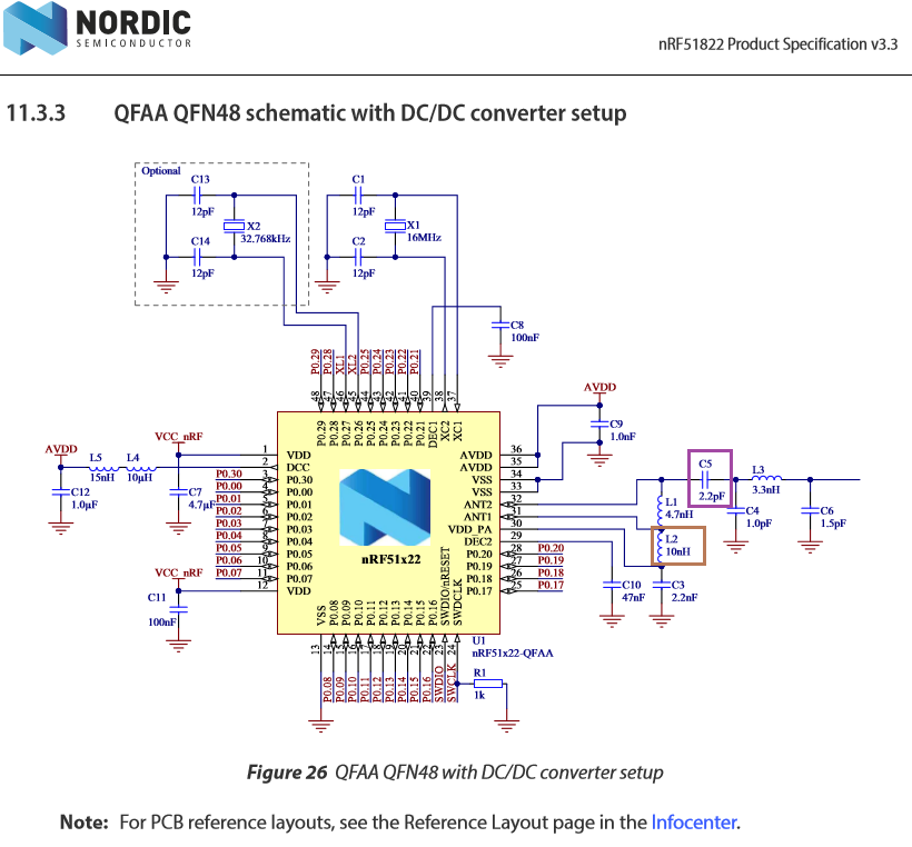
My client wants to choose the nRF51822-QFAA for his personal reasons

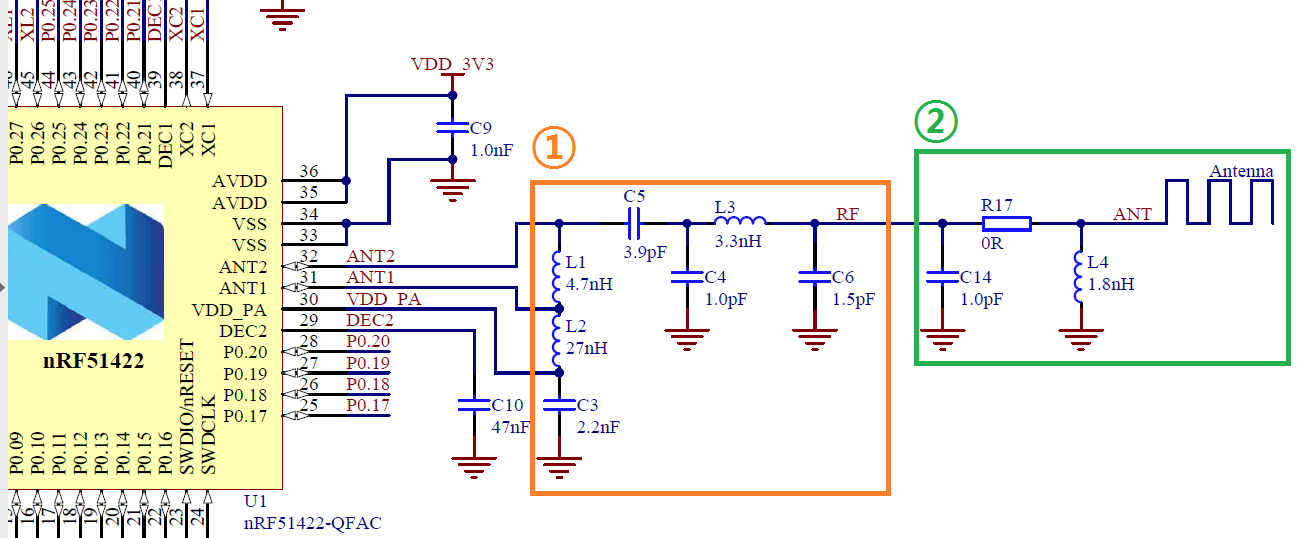
and he wants to use the meander antenna which is drawn at the PCA10031.

My questions are;

Antenna

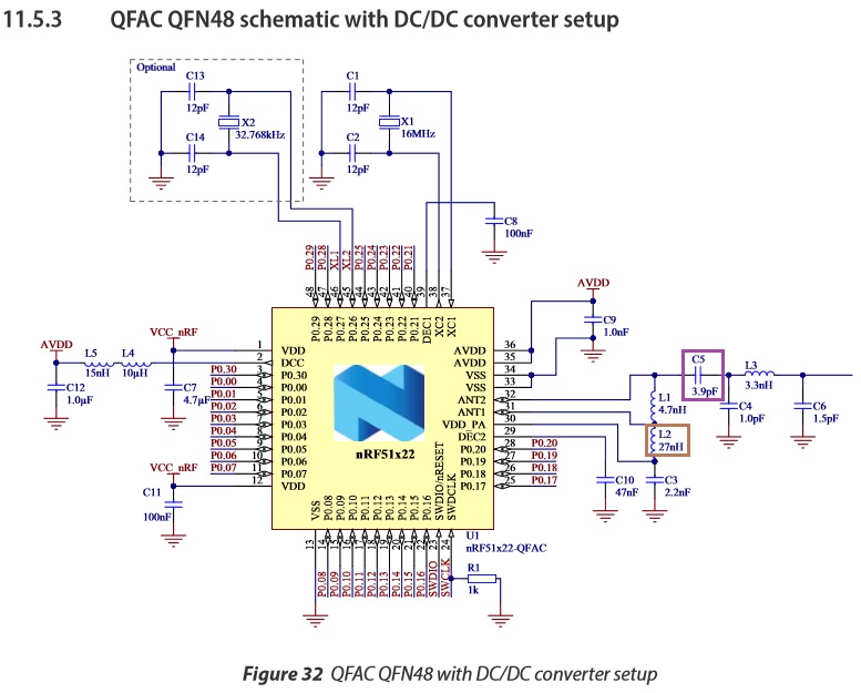
  1. Although the nRF51822-QFAA and the nRF51422 are similar,

I want to know whether it is fine to use the same values for the RF and the antenna components, the RLC values.

I'm planning to use the FR-4, 1.6mm thick, 2-layered PCB.

Can I use the same components, which is described in the PCA10031's schematic, when I work with nRF51822-QFAA?

// Edited 2017.05.09 - Summary & Compare referring Jørn's answer

nRF51822 Product Spec 3.3

nRF51422 Product Spec 3.1

QFAA

QFAC

  1. I just want to double check.InvertedF

Compared to the Inverted F antenna, the meander antenna, which is drawn on PCA10031, doesn't connect the antenna trace to the ground plane, right?

  1. By looking at the Digi-key number, the PCA10028 (Rev 1.2.0) used FC-135 32.7680KA-AC-ND, a product that uses 9pF as the load capacitance.

In this blog,

C1 = C2 = 2Cl - C_pcb - C_pin // C_pcb + C_pin is approximately 4 pF

I expected the capacitor values to be 14pF. However, the schematic tells that 12pF capacitors are populated.

Is there a reason for choosing the 12pF, such as

reducing the type of items for the pick and place machine or that Rev 1.2.0 board's C_pcb + C_pin value is approximately 6pF?

-Best Regards, MANGO

  • Hello MANGO

    The chip on the nRF51 dongle is the nRF51422-QFAC. This package is a little larger than the QFAA and QFAB packages and the matching network is therefore a little bit different to compensate. For the correct output network, please see the reference schematics for nRF51822-QFAA QFN48 on pages 82-87 of the nRF51822 product specification. Specifically you will see that the inductor L2, and capacitor C5 have different values.

    Correct, the meander antenna will not have the arm shorted to the ground plane as the IFA has. Please keep in mind that any changes to the PCA10031 antenna design will require changes to the antenna matching network encircled in green in your figure.

    At this time I'm afraid I don't have the specifics as to why 12 pF was chosen in this particular instance. I will need to look further into it and get back to you on that.

    Best regards

    Jørn Frøysa

  • Thanks for your answer, Jørn!

    1. In the product specifications, it is written as "nRF51x22". Just to double check,

    the nRF51822-QFAA / nRF51422-QFAA or the nRF51822-QFAC / nRF51422-QFAC use the same RLC components for network matching, right?

    1. I don't have the specifics as to why 12 pF was chosen in this particular instance. I will need to look further into it and get back to you on that.

    I see. Take your time. I hope to hear the news, if possible.

    -Best Regards, MANGO

  • My pleasure!

    1. Correct. Both the matching networks and the radio hardware is identical for the nRF51822 and nRF51422.

    2. I have passed the question on to a member of our design team, unfortunately he's travelling at the moment so I do not know when I'll get an answer.

  • I have received word from our member of the design team, and while he didn't have access to the specifics of the DK at the moment, due to him traveling, he did point out that the pins connected to the crystal have a capacitance of 4pF alone (page 42 of the nRF51822 product specification). Meaning the statement in the blog is incorrect, and the C_pin+C_board will be larger than 4pF. It is therefore quite possible the actual total is 6pF as you suggested.

  • Hi, Jørn. the pins connected to the crystal have a capacitance of 4pF alone. Meaning the statement in the blog is incorrect

    Really?! That's quite surprising. I always used that equation when designing custom PCBs.

    Then, Hmm... I ask questions about the load caps on another thread.

    Thanks for your time handling this question.

Related