This post is older than 2 years and might not be relevant anymore
More Info: Consider searching for newer posts

Question about the USB CDC ACM Example

Hi, before buying the PCA10056 kit, I have some questions about the USB CDC ACM example.

  1. I'm new to the USB CDC ACM.

At the Infocenter, it says that

This example shows how to use the CDC ACM USB class, commonly known as Virtual COM port.
The port can be opened and closed just like a traditional serial port.
Using a terminal emulator, for example putty,
send test data from the host computer to the development kit. LED 3 will blink.

COM

Does this mean that the nRF52840 can transfer or receive UART data without adding extra UART-USB ICs like FT232R?

If I use the USB CDC ACM example, can I read or write after I open the port from PuTTY just like using the UART example?

  1. When reading the sdk_config.h file, I couldn't find what pins are used for this example.

In the case of nRF52832-QFAA, the NFC1 and 2 pins were fixed to pin 11 and 12.

What about the nRF52840 and what pins are used for this example?

Is it the UART0 module used for the example, since it is enabled in the header file, and use pin 13 and 14?

Also, can I use any pins, except the power pins, to configure it as an USB related pins using PPI?

USB

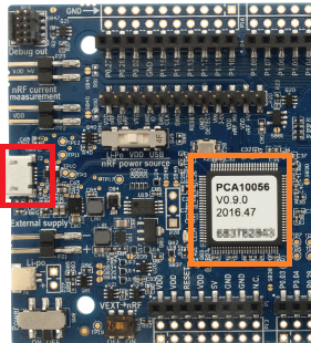
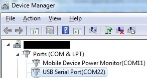
  1. Currently, I believe this example uses the USB connector that is connected the J-Link MCU, the Atmel MCU.

However, when creating a custom PCB which is related to Li-PO USB charging such as the BQ25010, I won't populate the J-Link MCU.

D+-

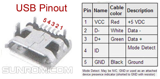
In this case, how should I configure my schematic wirings to connect the nRF52840's pins directly to the USB connector (D+/D-) when supplying 3.3 volts to the nRF52840?

  1. If I want to send a file, a 16KB mp3 file for instance, from the desktop to the nRF52840 MCU and write that data to the flash memory, should I use the CDC ACM example, or something else?

-Best Regards, MANGO

Parents
  • Hi Mango

    1. Yes. The USB interface in the nRF52840 allows it to implement FT232 like functionality without any additional hardware.
      Since the USB interface is fully programmable it can also do a lot more, as you can see by all the different USB examples available in the SDK.
      Just keep in mind that you need to connect to the second USB connector on the nRF52840 PDK to get access to the Nordic USB interface, otherwise you are just connecting to the Segger programming chip. From your terminal program the comport should look like any other, yes, and both read and write is supported.

    2. The USB interface has dedicated pins that are separate from the standard GPIO ports, and they can not be relocated to any other pins. The reason for this is that the USB interface pins require dedicated hardware that would be expensive and impractical to duplicate on multiple pins.

    The physical UART is only used for logging in this example, and the default configuration of UART0 (which allows it to connect to the UART interface in the Segger chip) is printed on the back of the nRF52840 PDK. This is the same configuration that we have always used, even before we got USB support in the chip, and it uses the CDC ACM functionality of the Segger chip to make the UART available on the PC.

    If you want to connect the Nordic CDC interface to a physical UART you could potentially use UART1 for this, allowing you to keep using UART0 for logging and debugging purposes.

    1. The J-Link USB connector is only used for programming/debugging and logging. To connect to the CDC in the Nordic you should add a second USB connection to the USB connector on the side of the kit, closer to the Nordic chip. You can connect both at the same time, or just connect to the Nordic connector (if you don't need logging or debugging).

    Regarding the layout you should refer to the reference schematic.
    As you can see the VBUS, D+ and D- lines should just be connected directly to the connector.

    1. If you want to transfer files you should probably consider the MSC examples instead, as they make the nRF52840 enumerate as a disk drive on the PC side. By default the example is configured to use the external memory chip on the nRF52840 PDK to store the files (showcasing the new QSPI interface in the chip), but it can also be configured to store to an external SD card.

    Edit: I have attached the CDC MSC hands on examples here:
    usbd_msc_cdc_asm_hands_on.zip
    usbd_msc_cdc_asm_hands_on_solution.zip

    Best regards
    Torbjørn

  • My bad, I forgot the repo was private. I have attached the files in my original reply.
    BR, Torbjørn

Reply Children
Related