Hi, before buying the PCA10056 kit, I have some questions about the USB CDC ACM example.
- I'm new to the USB CDC ACM.
At the Infocenter, it says that
This example shows how to use the CDC ACM USB class, commonly known as Virtual COM port.
The port can be opened and closed just like a traditional serial port.
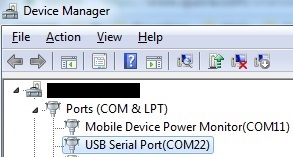
Using a terminal emulator, for example putty,
send test data from the host computer to the development kit. LED 3 will blink.

Does this mean that the nRF52840 can transfer or receive UART data without adding extra UART-USB ICs like FT232R?
If I use the USB CDC ACM example, can I read or write after I open the port from PuTTY just like using the UART example?
- When reading the
sdk_config.hfile, I couldn't find what pins are used for this example.
In the case of nRF52832-QFAA, the NFC1 and 2 pins were fixed to pin 11 and 12.
What about the nRF52840 and what pins are used for this example?
Is it the UART0 module used for the example, since it is enabled in the header file, and use pin 13 and 14?
Also, can I use any pins, except the power pins, to configure it as an USB related pins using PPI?

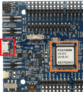
- Currently, I believe this example uses the USB connector that is connected the J-Link MCU, the Atmel MCU.
However, when creating a custom PCB which is related to Li-PO USB charging such as the BQ25010, I won't populate the J-Link MCU.

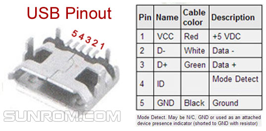
In this case, how should I configure my schematic wirings to connect the nRF52840's pins directly to the USB connector (D+/D-) when supplying 3.3 volts to the nRF52840?
- If I want to send a file, a 16KB mp3 file for instance, from the desktop to the nRF52840 MCU and write that data to the flash memory, should I use the CDC ACM example, or something else?
-Best Regards, MANGO

