
Dear colleagues,
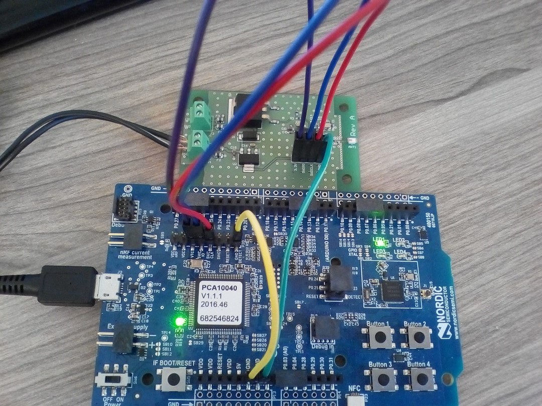
I am trying to erase / program the custom board ( with nRF52832 SoC installed) using nRF52-DK. The setup looks like that:
nRF52-DK Custom / External Board
VDD ------+-------------> VDD
VTG ----+/
GND ------------------------> GND
GND DETECT -----/
SWD IO -----------------> SWD IO
SWD CLK ----------------> SWD CLK
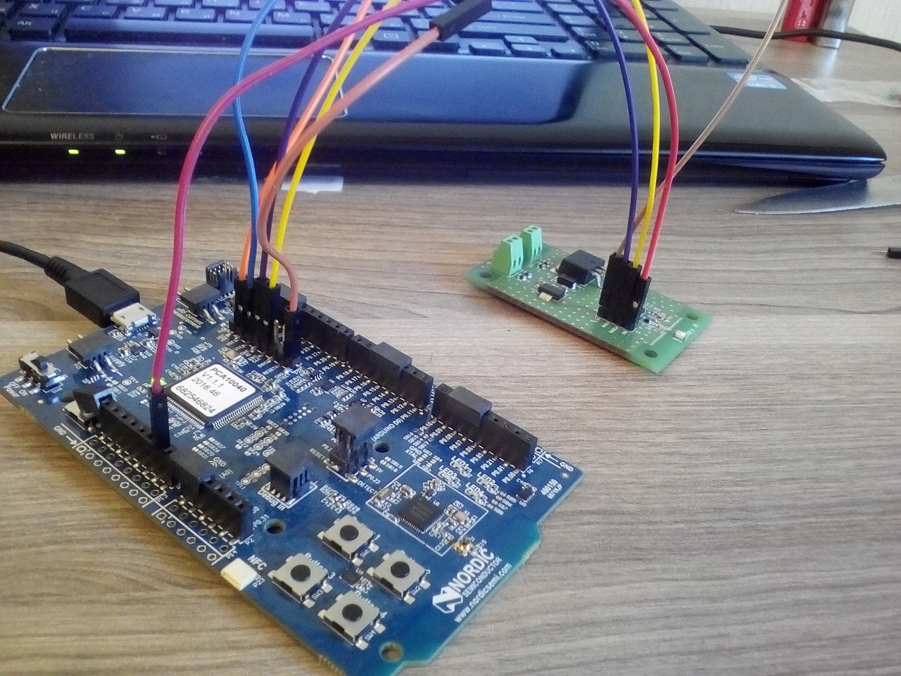
As the picture shows, the custom board nRF52-DK is powered from USB, and the custom board is powered from the nRF52-DK. The voltage on VDD (P20), VTG (P20), and external board is 2.86V. The voltage on SWDCLC and SWDIO (P20) is 2.63V.
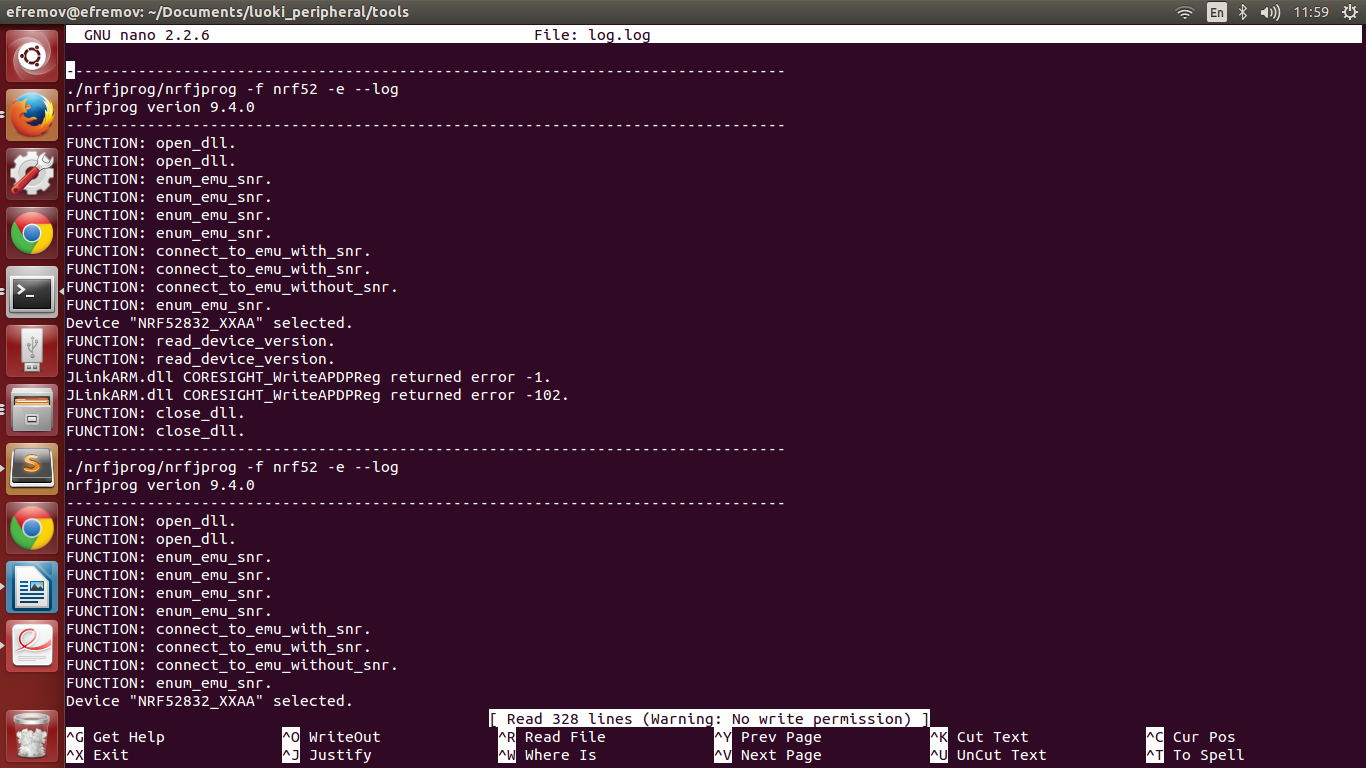
When I try to use nRFGO, the program just reloads whenever I click on motherboard's name. When I try to use nrfjprog, it shows the following error in log file:
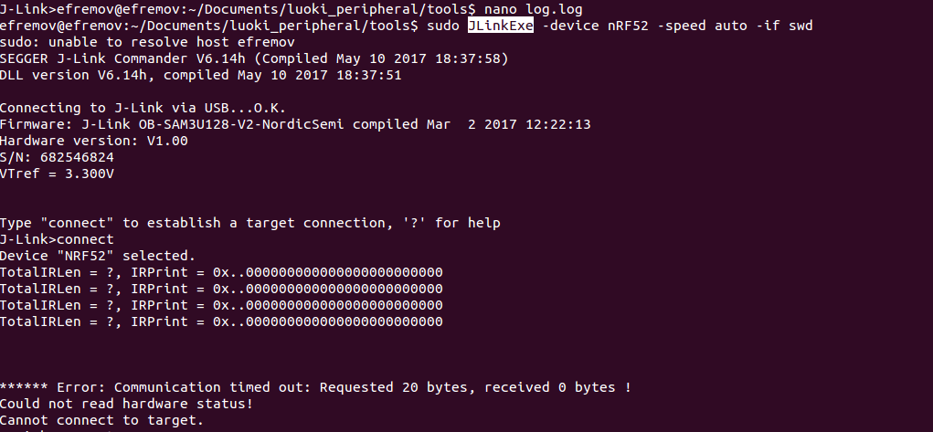
When I try to connect using JLinkExe, it shows the error:
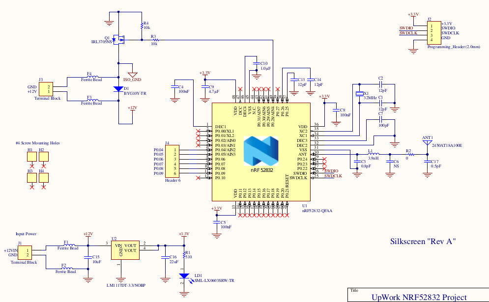
The schematic of the custom board is represented on the picture bellow:
I will appreciate any help!
P.S. programming the nRF52-DK (without custom board) works just fine.
UPDATE: when I power the custom board from the external power supply:
- custom board and DK not connected:
- voltage at DK: VDD - 2.88V, VTG - 0, SWDIO-2.65V, SWDCLC-2.65V
- voltage at custom board: VDD - 3.26V, SWDIO-3.21V, SWDCLC-0V
- custom board and DK are connected
nRF52-DK Custom / External Board
VTG ------+-------------> VDD
GND ------------------------> GND
GND DETECT -----/
SWD IO -----------------> SWD IO
SWD CLK ----------------> SWD CLK
- VTG - 3.26V, SWDIO: 3.30V, SWDCLC - 0.52V on both
- if I disconnect SWDCLCs, when SWDCLC at DK is 3.56V, at custom board - 0V
- if I disconnect SWDIOS, when SWDIO at DK is 3.56V, at custom board - 3.21V
The setup was tested with another nRF52-DK and it also did not work, so DK is not the problem.
The closer photo of how the chip is mounted is attached: DSC00364.png


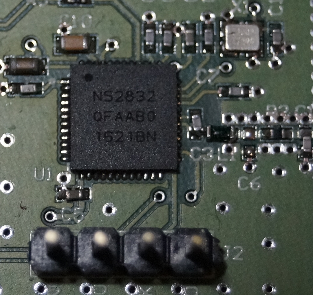