This post is older than 2 years and might not be relevant anymore
More Info: Consider searching for newer posts

nRF52840 TWIM

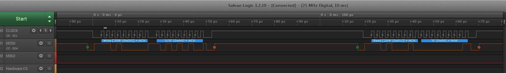
First try to create a TWIM driver from scratch without any DMA. Following the steps in the OPS I get mixed behavior and only the chapter with DMA generates any clock and data on the interface. Without setting Master enable bit nothing will start and there is no reference in the non DMA flow diagram. Anyhow when using Master bit I get all TXD data on the bus but not RXD.

I use Prev-DK board with SDOF Stick connected to P0.27/P0.26 at 100kHz.

This is my flow right now:

// ***** INIT *****
#define USED_I2C_BLOCK 0x40003000

output_32( USED_I2C_BLOCK+I2C_TXD_MAXCNT_REG, 2 );

// enable master mode
output_32( USED_I2C_BLOCK+I2C_ENABLE_REG, 1 );

// ***** TRANSMITT *****

// send start condition
output_32( USED_I2C_BLOCK+I2C_STARTTX_REG, 1  );

// wait for int

// write data (slave address)
output_32( USED_I2C_BLOCK+I2C_TXD_REG, (SlaveAddress<<1) );

// wait for int

// write data (register address)
output_32( USED_I2C_BLOCK+I2C_TXD_REG, RegAddr );

// wait for int

// send stop bit
output_32( USED_I2C_BLOCK+I2C_STOP_REG, 1 );

// wait for int

// ***** RECEIVE *****

output_32( USED_I2C_BLOCK+I2C_RXD_MAXCNT_REG, DataBufferSize );

// enable master mode
output_32( USED_I2C_BLOCK+I2C_ENABLE_REG, 1 );

// send start condition
output_32( USED_I2C_BLOCK+I2C_STARTRX_REG, 1 );

// wait for int

// send read slave address
output_32( USED_I2C_BLOCK+I2C_TXD_REG, (SlaveAddress<<1)+1 );

// wait for int

while ( DataBufferSize-- )
{
	if ( DataBufferSize == 0 )
	{
		// send stop bit
		output_32( USED_I2C_BLOCK+I2C_STOP_REG, 1 );
	}

	// wait for int

	// read data
	*DataByte++ = input_32( USED_I2C_BLOCK+I2C_RXD_REG );
}
Parents
  • Hi,

    Assuming that your output_32() function is bug free;

    1. Are you sure it is necessary to left shift the slave address?
    2. Do you really need to add 1 to the address when reading from a slave? The TWI module takes care of that.
    3. Where do you set the TX and RX buffer?

    Here is one way to use do a "bare bone" TX/RX transfer:

    static void twi_transfer()
    {
        NRF_TWIM0->ENABLE = TWIM_ENABLE_ENABLE_Disabled << TWIM_ENABLE_ENABLE_Pos;
        NRF_TWIM0->SHORTS = (TWIM_SHORTS_LASTTX_STOP_Enabled << TWIM_SHORTS_LASTTX_STOP_Pos) | 
                            (TWIM_SHORTS_LASTRX_STOP_Enabled << TWIM_SHORTS_LASTRX_STOP_Pos);
        
        
        NRF_TWIM0->PSEL.SCL = MPU_TWI_SCL_PIN;
        NRF_TWIM0->PSEL.SDA = MPU_TWI_SDA_PIN;
        NRF_TWIM0->FREQUENCY = TWI_FREQUENCY_FREQUENCY_K400;
        NRF_TWIM0->ADDRESS = MPU_ADDRESS;
        
        NRF_TWIM0->TXD.PTR = (uint32_t)&p_tx_buffer;
        NRF_TWIM0->TXD.MAXCNT = 1;
        
        NRF_TWIM0->RXD.PTR = (uint32_t)&p_rx_buffer;
        NRF_TWIM0->RXD.MAXCNT = 1;
        
        NRF_TWIM0->ENABLE = TWIM_ENABLE_ENABLE_Enabled << TWIM_ENABLE_ENABLE_Pos;
        
        NRF_TWIM0->EVENTS_LASTTX = 0;
        NRF_TWIM0->TASKS_STARTTX = 1;
        
        // Wait for TX to complete
        nrf_delay_us(100);
        
        NRF_TWIM0->TASKS_STARTRX = 1;
    }
    

    You can also use:

    NRF_TWIM0->SHORTS = (TWIM_SHORTS_LASTTX_STARTRX_Enabled << TWIM_SHORTS_LASTTX_STARTRX_Pos)
    

    To start an RX immediately after the TX is completed.

    I don't know what is going on inside output_32(), but you seem to know how to use register base addresses and register offsets, so I think the above code should be easy for you to port.

    EDIT: The above code will produce the following action on the TWI bus: image description

    You can see that the TWI module takes care of left shifting of your 7-bit address and adds the READ bit automatically.

    EDIT 2: I have reviewed the case again and noticed a few more things that I didn't see initially:

    Since you talk about DMA and use the I2C_TXD_MAXCNT_REG register, but at the same time also talk about using TRD/TXD registers directly it sounds like you are cherry picking features from the legacy TWI module and the new TWIM module.

    • The legacy TWI module is basically "copy-pasted" hardware from the nRF51. It has a lot less features than the new module in nRF52. It does not have any DMA features for example. If you want to use the legacy module and use TXD/RXD registers directly you can only use the features available in this particular module. Legacy TWI documentation. With the legacy module you will have to update the TXD register for every byte you want to send.

    • The new module in nRF52 is an extension of the legacy module and hence shares some of the same registers. If you want to use DMA you will have to use the features documented here and you cannot use RXD/TXD directly.

Reply
  • Hi,

    Assuming that your output_32() function is bug free;

    1. Are you sure it is necessary to left shift the slave address?
    2. Do you really need to add 1 to the address when reading from a slave? The TWI module takes care of that.
    3. Where do you set the TX and RX buffer?

    Here is one way to use do a "bare bone" TX/RX transfer:

    static void twi_transfer()
    {
        NRF_TWIM0->ENABLE = TWIM_ENABLE_ENABLE_Disabled << TWIM_ENABLE_ENABLE_Pos;
        NRF_TWIM0->SHORTS = (TWIM_SHORTS_LASTTX_STOP_Enabled << TWIM_SHORTS_LASTTX_STOP_Pos) | 
                            (TWIM_SHORTS_LASTRX_STOP_Enabled << TWIM_SHORTS_LASTRX_STOP_Pos);
        
        
        NRF_TWIM0->PSEL.SCL = MPU_TWI_SCL_PIN;
        NRF_TWIM0->PSEL.SDA = MPU_TWI_SDA_PIN;
        NRF_TWIM0->FREQUENCY = TWI_FREQUENCY_FREQUENCY_K400;
        NRF_TWIM0->ADDRESS = MPU_ADDRESS;
        
        NRF_TWIM0->TXD.PTR = (uint32_t)&p_tx_buffer;
        NRF_TWIM0->TXD.MAXCNT = 1;
        
        NRF_TWIM0->RXD.PTR = (uint32_t)&p_rx_buffer;
        NRF_TWIM0->RXD.MAXCNT = 1;
        
        NRF_TWIM0->ENABLE = TWIM_ENABLE_ENABLE_Enabled << TWIM_ENABLE_ENABLE_Pos;
        
        NRF_TWIM0->EVENTS_LASTTX = 0;
        NRF_TWIM0->TASKS_STARTTX = 1;
        
        // Wait for TX to complete
        nrf_delay_us(100);
        
        NRF_TWIM0->TASKS_STARTRX = 1;
    }
    

    You can also use:

    NRF_TWIM0->SHORTS = (TWIM_SHORTS_LASTTX_STARTRX_Enabled << TWIM_SHORTS_LASTTX_STARTRX_Pos)
    

    To start an RX immediately after the TX is completed.

    I don't know what is going on inside output_32(), but you seem to know how to use register base addresses and register offsets, so I think the above code should be easy for you to port.

    EDIT: The above code will produce the following action on the TWI bus: image description

    You can see that the TWI module takes care of left shifting of your 7-bit address and adds the READ bit automatically.

    EDIT 2: I have reviewed the case again and noticed a few more things that I didn't see initially:

    Since you talk about DMA and use the I2C_TXD_MAXCNT_REG register, but at the same time also talk about using TRD/TXD registers directly it sounds like you are cherry picking features from the legacy TWI module and the new TWIM module.

    • The legacy TWI module is basically "copy-pasted" hardware from the nRF51. It has a lot less features than the new module in nRF52. It does not have any DMA features for example. If you want to use the legacy module and use TXD/RXD registers directly you can only use the features available in this particular module. Legacy TWI documentation. With the legacy module you will have to update the TXD register for every byte you want to send.

    • The new module in nRF52 is an extension of the legacy module and hence shares some of the same registers. If you want to use DMA you will have to use the features documented here and you cannot use RXD/TXD directly.

Children
Related