This post is older than 2 years and might not be relevant anymore
More Info: Consider searching for newer posts

External programming of nrf51/52 using nrf51/52 dk's

Is there any documentation as to how to connect a nrf52 chip (as found on the nRF52832 BT Module with Header Pins (www.analoglamb.com/.../) or the nrf51 on the Adafruit bleFriend (www.adafruit.com/.../2479).

I did see that there are two connectors on the DK's, P19 and P20. P20 has pins marked on the connector. I cannot find pinout for P19.

The analoglamp.com has two connectors, both 2x9, which bring out the nrf52832 pins. On one of these I see the pins SCLK and SDO which I think are SWDCLK and SWDIO.

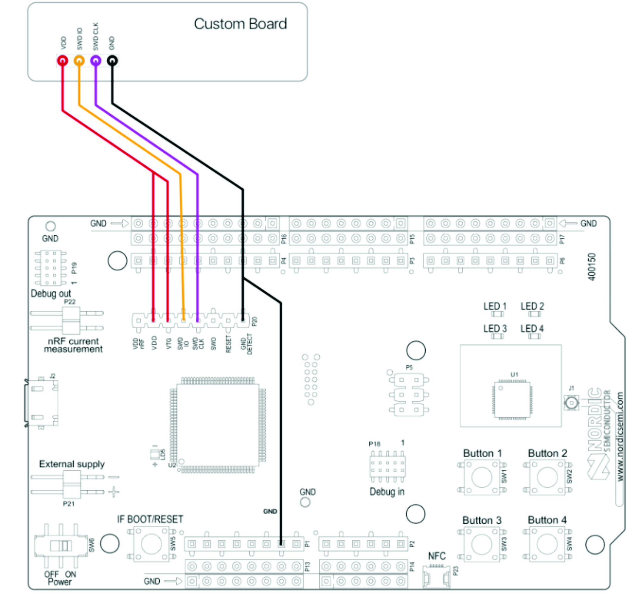
The adafruit has pins labeled swc, swd, 3volt, and ground. I think the swc and swd correspond to the swdclk and swdio pins on the nrf52832. I see that the P20 has pins VDD (I think this is input), swdclk, swdio, gnd detect and VTG (I don't know what this pin does ??).

I found this diagram. Is it correct?? nrf dk external programming.jpg

thanks for the help,

Richard Ferraro

thanks, Richard Ferraro

Parents
  • Is this diagram correct? nrf dk external programming.jpg

    The documentation indicates that a switch to the external nrf52 is made when a voltage is sensed.

    As shown in the diagram attached, should this analoglamb module provide its voltage and gnd to the VDD pin?

    What is the VTG pin on P20 of the PCA10040?

    On the analoglamb module, there is a pin opposite gnd called COV. Is this where power to the module should be provided?

    I have now purchased 7 of your dk's.

    thank you,

    Richard Ferraro

  • VTG pin on P20 "senses" the voltage level in the target board; it does NOT provide power. You can use VDD pin on P20 to power the target module.

Reply
  • VTG pin on P20 "senses" the voltage level in the target board; it does NOT provide power. You can use VDD pin on P20 to power the target module.

Children
No Data