
Hi guys, me again.
I was very confused with my current process on developing with nrf chip now... so I would like to post my develop step and some problems I had so maybe you could give me some advises. I think I maybe stuck in my own circle.
I'm sorry to give such a long post here.
I have read through the tutorial about the nrf51 DK and BLE and many post about changing clock source for example. For the DK, I could successfully load the code to the DK, for example the UART transmission example and use my phone to communicate with it.
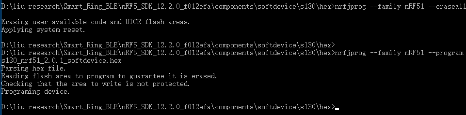
For the step for developing the DK, I first load the softdevice using command line tool, the softdevice I load to the DK is from SDK 12.2, s130, version is 2.0.1. Then I open the example in Keil, build up and then load to the DK, it was fine.
So, then I would like to try the code with my own board. First, I was using the nrf51822 module from Taiyo Yuden Inc, which the board them made doesn't have an external clock source, so I have changed the clock source to the internal RC clock source with the following code in example code in Keil5.
//set up clock source
 nrf_clock_lf_cfg_t rc_cfg =
{
    .source = NRF_CLOCK_LF_SRC_RC,
    .rc_ctiv = 16,
    .rc_temp_ctiv = 2,
 };

// Initialize SoftDevice.
SOFTDEVICE_HANDLER_INIT(&rc_cfg, NULL);
For the board I'm using, please refer to the following image:
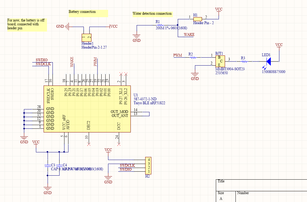
I connect the SWD interface to the Jlink and since the board doesn't have the reset and SWO, I only use the SWDIO and SWCLK to the Jlink. Then with the Jlink connected, I used command line tool to program the softdevice to this board. The command line tool shows the softdevice has been programmed.
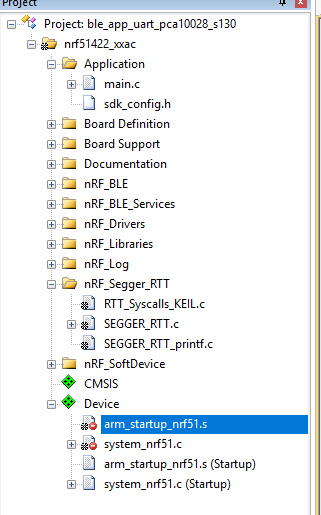
Then I open the example in Keil5, for this time using the uart example also. I build and then load to the board.
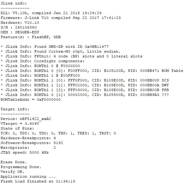
After this, I open my phone and use the nordic app to scan the board, there is nothing. For my point, I was trying to see if I could program the board to be scanable and also can be connected with phone, then develop some other functionalities base on that, but I could not see the board.
Did I do anything wrong with the procedure?
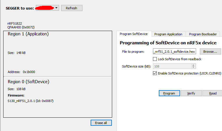
That was what I have done with the Taiyo Yuden board. Since the board has all the pins under the chip, I thought maybe there is something wrong with my soldering, so I used another chip which all the pins are on the side of the board so I could see actually I have soldered them correctly. The board I'm using is this one.
For this board, I was trying some similar procedure.
I first used the nRFGo studio to program the softdevice, same version from the previous one.
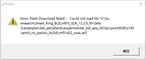
Then I tried to load the example code from Keil, but I got an error that the Flash Downloaded fail.
At first, the error says Flash Downloaded fail - could no open XXX\XXX\XXX.axf file.
 ....I was so confuse by now....
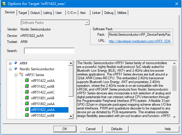
Another concern is that, if I change the device to the nrf51822_xxAA which I used with the board, the device became red and there is no update option to use for the files.
It was a long post, but I you have any idea which step I did wrong, please let me know.
Thanks
