This post is older than 2 years and might not be relevant anymore
More Info: Consider searching for newer posts

P0.09 and P0.10 on nRF52810

Hi,

I'm developing on nrf52810 using the SDK14.1.0 and I've take as starting point a template application that targets nRF52810 running on the nRF52 Development Kit. But I'm working on nrf52810 hardware, NOT the nrf52DK, so I've made preprocessor and startup files adjustments as indicated in documentation.

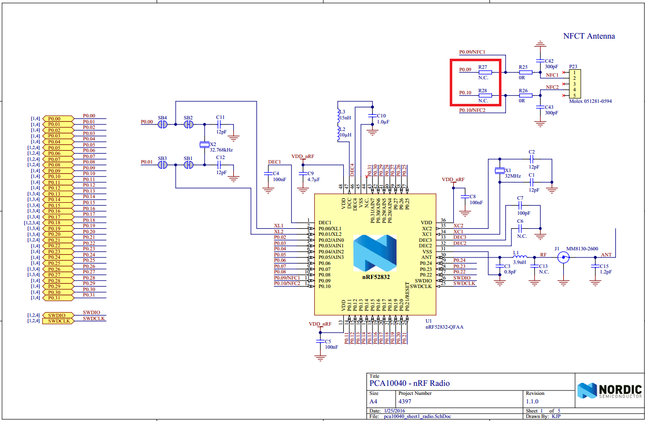
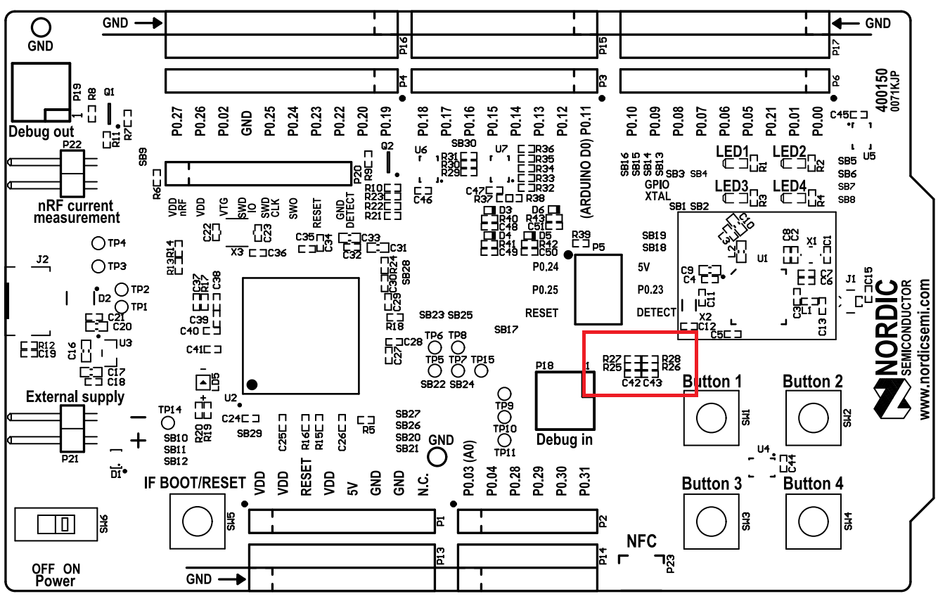
I want to use P0.09 as digital output and I've read many questions about using this pins as GPIO instead of NFC. I understand the issue when using nrf52DK and default settings in SDK, but nrf52810 has no support for NFC so I think this pins should be default configured as GPIO.

For testing I'm generating a clock signal which is properly driven through pins P0.28, P0.30 and P0.12.

What's missing?

Thanks!

Parents Reply
  • My apologies, I forgot about that.

    Anyway. I did a quick test of pin 9 and 10 on an nRF52810 myself. I based my test on the SDK_14.1.0\examples\peripheral\uart\pca10040e example. I removed all the UART stuff and simply toggled pin 9 and 10 in 1 second intervals. It seems to work fine. No special porting was required. Can you try this hex file that works on my kit? nrf52810_xxaa_nfc_toggle_test.hex

    How are you generating your clock signal? Are you using GPIOTE and PPI for example? Can you upload a hex file or code that I can try?

Children
Related