This post is older than 2 years and might not be relevant anymore
More Info: Consider searching for newer posts

RTC jittering and lacking control of frequency

I am using the RTC to generate a square wave signal.

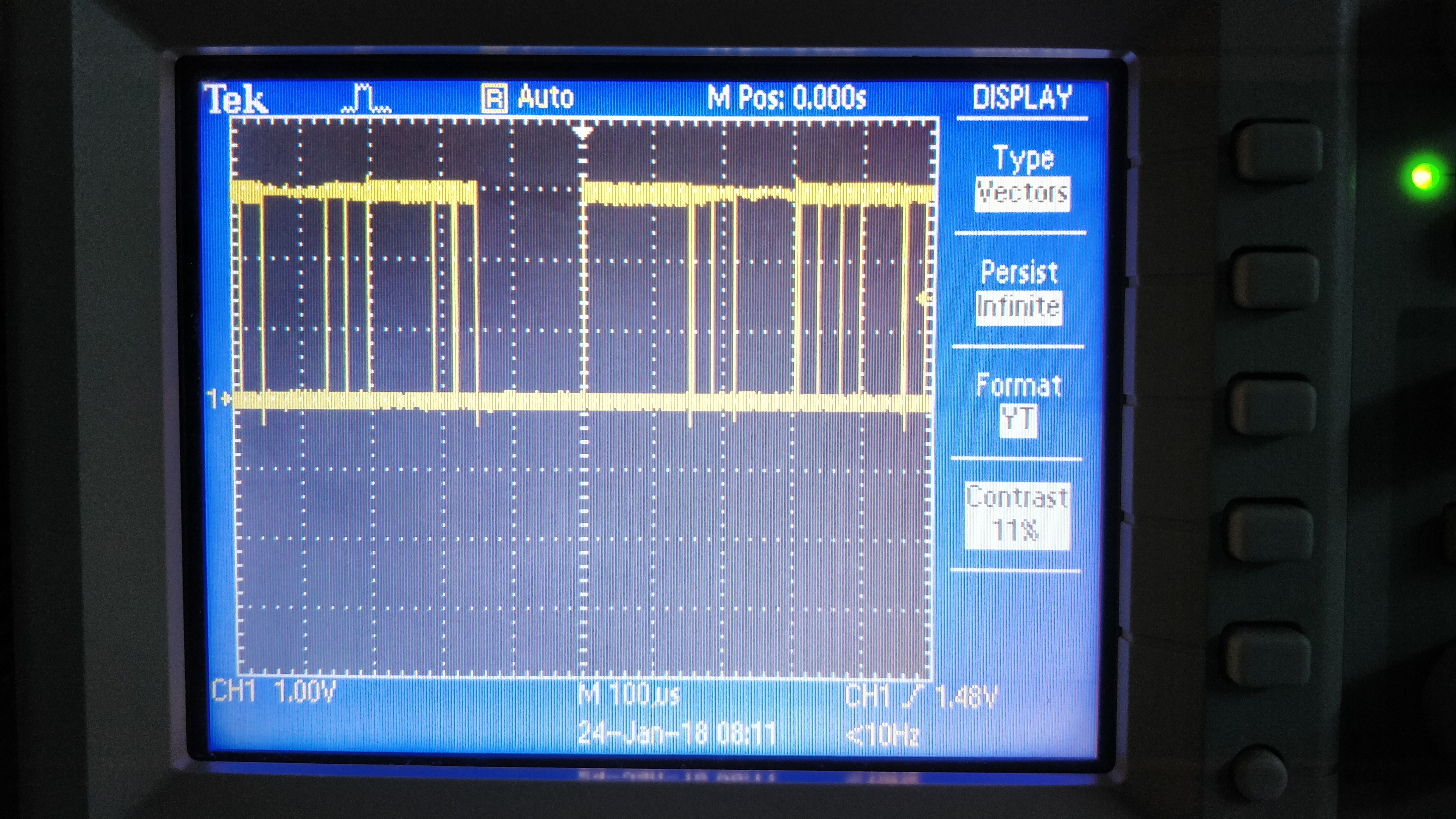
I have two issues. One is that nothing I do on the prescaler or the Count Compare is having an influence on the frequency produced. The other is that I have significant jitter on the time axis (see image below).

Here is my code that currently yields a frequency of 3.3 kHz:

NRF_CLOCK->LFCLKSRC = (CLOCK_LFCLKSRC_SRC_Xtal << CLOCK_LFCLKSRC_SRC_Pos);
NRF_CLOCK->EVENTS_LFCLKSTARTED = 0;
NRF_CLOCK->TASKS_LFCLKSTART = 1;
while (NRF_CLOCK->EVENTS_LFCLKSTARTED == 0){}
NRF_CLOCK->EVENTS_LFCLKSTARTED = 0;
NRF_RTC1->PRESCALER = 4; 
NRF_RTC1->EVTENSET = RTC_EVTENSET_COMPARE0_Msk;
NRF_RTC1->CC[0] = 10;
NRF_PPI->CH[1].EEP = (uint32_t)&NRF_RTC1->EVENTS_COMPARE[0];
NRF_PPI->CH[1].TEP = (uint32_t)&NRF_GPIOTE->TASKS_OUT[1];
NRF_PPI->CH[2].EEP = (uint32_t)&NRF_RTC1->EVENTS_COMPARE[0];
NRF_PPI->CH[2].TEP = (uint32_t)&NRF_RTC1->TASKS_CLEAR;
NRF_GPIOTE->CONFIG[1] =((GPIOTE_CONFIG_MODE_Task       << GPIOTE_CONFIG_MODE_Pos)
                        |(CONV                         << GPIOTE_CONFIG_PSEL_Pos)
                        |(GPIOTE_CONFIG_POLARITY_Toggle << GPIOTE_CONFIG_POLARITY_Pos)
                        |(GPIOTE_CONFIG_OUTINIT_Low     << GPIOTE_CONFIG_OUTINIT_Pos));

NRF_RTC1->TASKS_START = 1;

Is the PPI channel resetting the counters necessary / is there a better way to do it?

What am I doing wrong for setting the frequency? Is the jitter something to be expected? I cannot resort to using TIMERX as they are already occupied (SD, SPI and another square wave at 4 MHz).

RTC Jitter

  • well for a start nowhere in that code do you actually start the RTC timer. Nor enable the counter events either (EVTEN)

  • I had the rtc start in there but must have somehow lost it while playing around with the code. I added it and it does not change anything. I also added the line NRF_RTC1->EVTENSET = RTC_EVTENSET_COMPARE0_Msk; But still the outcome is the same.

  • well the rest looks fine to me now you added those two. So what pin are you using, is it already used for something else, are you sure you're actually measuring the right thing because you should get absolutely nothing at all or the correct thing. The random noise makes no sense at all and I can't even really tell what the scale is on that plot. You don't say which chip you're using either by the way which you always should. eg if you're using the nRF52 and have selected pin 9 or 10, you just picked the NFC pin and could get just about anything.

  • @RK: To be fair, he mentions nRF51 in the tags in his question.

    @stephbur: Another thing that is missing in the code in your question is the enabling of your PPI channels. Try to add this:

    NRF_PPI->CHEN = (PPI_CHEN_CH1_Enabled << PPI_CHEN_CH1_Pos) | (PPI_CHEN_CH2_Enabled << PPI_CHEN_CH2_Pos);
    

    I tested your code on an nRF51 DK and toggled LED_4. It worked fine. Output frequency was a stable 321.3Hz. The random square waves are pretty odd though. Are you sure you are not measuring on your SPI bus or something? It could be some sort of serial signals.

Related