This post is older than 2 years and might not be relevant anymore
More Info: Consider searching for newer posts

UARTE ENDTX event latency

According to the User Guide,

After each byte has been sent over the TXD line, a TXDRDY event will be generated.


When all bytes in the TXD buffer, as specified in the TXD.MAXCNT register, have been transmitted, the
UARTE transmission will end automatically and an ENDTX event will be generated.

Are the above events generated when the stop bit of the last byte is transmitted? Or are these events generated as soon as the last byte is shifted out of internal HW shift register (6-byte internal HW FIFO)?

If we have a strict time requirement to set a IO line immediately (within 10 micro secs) after sending the last byte, is that possible? What kind of latency to be expected between the stop bit of the last byte and ENDTX event published? We plan to use 1M BAUD.

  • Hello,

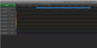
    I tested with 115200 baud rate, and a PPI set up to change a pin at the ENDTX event. As you can see, the event is set at the very end of the last payload bit, and right before the stop bit. Screenshot below shows the TX line on Channel 0 and the pin that switched on ENDTX on Channel 1.

    I also tested it with the 1M baudrate. As you can see there is a tiny delay, but it is less than 0.3µs.

    The same delay is on the 115200 baudrate, but of course it is neglectable with that baudrate.

    Best regards,

    Edvin

  • If you want to test yourself, here is the piece of code that I used to test:

    void attach_ENDTX_to_pin(uint32_t pinselect)
    {
        NRF_GPIOTE->CONFIG[ENDTX_GPIOTE_CH] =   GPIOTE_CONFIG_MODE_Task << GPIOTE_CONFIG_MODE_Pos |
                                                GPIOTE_CONFIG_POLARITY_Toggle << GPIOTE_CONFIG_POLARITY_Pos |
                                                pinselect << GPIOTE_CONFIG_PSEL_Pos |
                                                GPIOTE_CONFIG_OUTINIT_High << GPIOTE_CONFIG_OUTINIT_Pos;
        
        NRF_PPI->CH[ENDTX_GPIOTE_CH_A].EEP  =   (uint32_t)&NRF_UARTE0->EVENTS_ENDTX;
        NRF_PPI->CH[ENDTX_GPIOTE_CH_A].TEP  =   (uint32_t)&NRF_GPIOTE->TASKS_CLR[ENDTX_GPIOTE_CH];
        
        NRF_PPI->CHENSET = (1 << ENDTX_GPIOTE_CH_A);
    }
    
    int main(void)
    {
        ...init_uart...
        
        attach_ENDTX_to_pin(22);    //use e.g. pin 20 to use LED4 (nRF52832)
        
        printf("Start: \r\n");
    
    }

  • Thanks Edvin.

    For our use case, the transmit section and receive section of hardware cannot be enabled at the same time. If I have to wait until all the bytes are completely transmitted, this method may not work because the transmit section would be turned off before the stop bit of the last byte is transmitted. Ther could be framing errors on other side.

    Some MCUs have TX_COMPLETE interrupt which is asserted after stop bit is sent out.

    How do I address this scenario?

  • Hello,

    If you need to add a delay after the ENDTX event, you must use a timer. I have added this in the code below:

    #define ENDTX_GPIOTE_CH 0
    #define ENDTX_GPIOTE_CH_A 0
    #define TIMER_CAPTURE_CH 1
    #define TIMER_COMPARE_CC_NUM 0
    #define TIMER_CAPTURE_DELAY_US 2
    
    #define TIMER_RELOAD 1024
    #define TIMER_RELOAD_CC_NUM 5
    
    void timer_init(void)
    {
        NRF_TIMER3->BITMODE                 = TIMER_BITMODE_BITMODE_24Bit << TIMER_BITMODE_BITMODE_Pos;
        NRF_TIMER3->PRESCALER               = 4;
        NRF_TIMER3->SHORTS                  = TIMER_SHORTS_COMPARE0_CLEAR_Msk << TIMER_RELOAD_CC_NUM;
        NRF_TIMER3->MODE                    = TIMER_MODE_MODE_Timer << TIMER_MODE_MODE_Pos;
        NRF_TIMER3->CC[TIMER_RELOAD_CC_NUM] = TIMER_RELOAD;
        NRF_TIMER3->CC[TIMER_COMPARE_CC_NUM]= TIMER_CAPTURE_DELAY_US;
    }
    
    void timer_start(void)
    {
        NRF_TIMER3->TASKS_START = 1;
    }
    
    void attach_ENDTX_to_pin(uint32_t pinselect)
    {
        NRF_GPIOTE->CONFIG[ENDTX_GPIOTE_CH]     = GPIOTE_CONFIG_MODE_Task << GPIOTE_CONFIG_MODE_Pos |
                                                  GPIOTE_CONFIG_POLARITY_Toggle << GPIOTE_CONFIG_POLARITY_Pos |
                                                  pinselect << GPIOTE_CONFIG_PSEL_Pos |
                                                  GPIOTE_CONFIG_OUTINIT_High << GPIOTE_CONFIG_OUTINIT_Pos;
        
        NRF_PPI->CH[ENDTX_GPIOTE_CH_A].EEP      = (uint32_t)&NRF_UARTE0->EVENTS_ENDTX;
        NRF_PPI->CH[ENDTX_GPIOTE_CH_A].TEP      = (uint32_t)&NRF_TIMER3->TASKS_CLEAR;
        NRF_PPI->FORK[ENDTX_GPIOTE_CH_A].TEP    = (uint32_t)&NRF_GPIOTE->TASKS_SET;
        NRF_PPI->CH[TIMER_CAPTURE_CH].EEP       = (uint32_t)&NRF_TIMER3->EVENTS_COMPARE[TIMER_COMPARE_CC_NUM];
        NRF_PPI->CH[TIMER_CAPTURE_CH].TEP       = (uint32_t)&NRF_GPIOTE->TASKS_CLR[ENDTX_GPIOTE_CH];
        
        
        NRF_PPI->CHENSET = (1 << ENDTX_GPIOTE_CH_A) | (1 << TIMER_CAPTURE_CH);
    }
    
    int main(void)
    {
        ...init_uart...
        timer_init();
        timer_start();
        attach_ENDTX_to_pin(22);
    }

    This will toggle the pin after TIMER_CAPTURE_DELAY_US microseconds.

    You can use the EGU (event generation unit) to do something useful instead of toggling the pin, but as you can see, the pin will go low (in this case) 2µs after the last byte is sent. 

Related