
Hi all,
Please find my following current measurement resuls in the pwr_mgmt example using a nRF52 preview DK and SDK 13
My setup is as follow:
- SB40 is cut
- SW6 is at nRF ONLY
- SW10 is at ON (3.0V external supply to P21, 3.3V supply the current rises to 8uA and will not come down)
- SW9 is at VDD
- Current is measured through P22 with a current probe and a 10 ohm resistor is mounted
- USB is connected to J2
- UART and logger module is disabled through sdk_config.h
- The solder joint for the onboard flash is disconnected
Should I flip SW8 to ON or OFF?
When I flip it to ON, I obtained the following measurement:
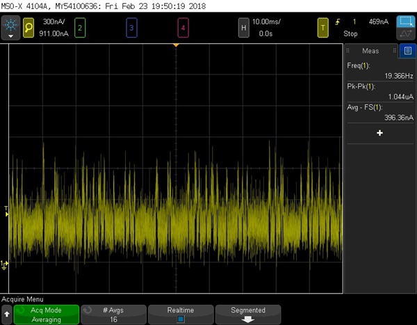
System on, low power mode:
System off, after pressing Button 1:

The result seems to make sense but there are a lot of little peaks in the waveform.
When I zoomed out, there is another peak which doesn't seem like noise:
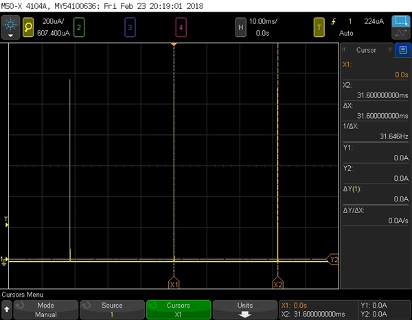
The peak lasts for around 300ms and repeats for at 30Hz. I wonder if this is the capacitor peaks mentioned in this link:
but it is way too long than what is mentioned in the link (10-15us) and it is definitely not the peak for the app timer created in the pwr_mgmt module.
When I flip it to OFF:
The current immediately rises:
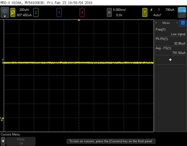
This also happends when I plugged out the USB cable connected to J2, but the SoC should still be working since I use an external supply for it but why it has such radical behavior when the sw is flipped to ON and OFF? What am I missing here?
Thanks!


