This post is older than 2 years and might not be relevant anymore
More Info: Consider searching for newer posts

BOR and power Fail comparator

Hi,

can you please to provide a more information regard power up sequence?

for example:

we would like to use DC2DC (instead LDO) with CR2032 battery.

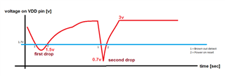
the PCB have nRF52832 and battery holder, while I put in the battery to battery holder there is chanse for a voltages drop for example : 

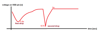
once VDD supplied by "high enough voltage" then boot loader start with FW upload from internal FLASH, if at the time that FW uploaded from internal FLASH happened some drop voltage to X and time of drop is Y.

please explain :

1. what the time and  stablle value of voltage is mandatory for start process of FW upload from internal FLASH to RAM ? (I think that the FW run on the RAM not on the FLASH)

 2. what happened while FW uploaded from internal FLASH to RAM and some drop occured, so bootloader will be restart  uploading process ?

3. bootloader have some CRC checking about uploaded FW?

Parents
  • Hi Sergey,


    I took the liberty of modifying your curve:

    Here's two states, one on the downward slope (1), which will generate a brown-out-detection

    and the upwards slope (2), which will start a power-on-reset (POR).

    The device will go out of POR mode after the VDD_NRF has reached 1.7V _and_ the parameter "tpor" has elapsed.

    The nRF will be kept in reset for a given amount of time after VDD_NRF >= 1.7V, based on the rise-time of your power supply, as specified here:

    http://infocenter.nordicsemi.com/topic/com.nordic.infocenter.nrf52832.ps.v1.1/power.html?cp=2_1_0_17_9_1#unique_744469603 

    1. what the time and  stablle value of voltage is mandatory for start process of FW upload from internal FLASH to RAM ? (I think that the FW run on the RAM not on the FLASH)

    The firmware is located in flash. The CPU will start executing after "tpor" has elapsed, and will setup your RAM based on your program located in flash.

     2. what happened while FW uploaded from internal FLASH to RAM and some drop occured, so bootloader will be restart  uploading process ?

    If a bootloader (DFU) process is on-going and the power-supply is disrupted, you will be RESET and boot back into the bootloader. 

    In this case the bootloader will know where it was in the process, and continue from there.

    3. bootloader have some CRC checking about uploaded FW?

    The DFU checks it's own settings area to validate the current installed application (CRC checksum) and see what state it is in.

    If there has been a DFU-process that has been disrupted, it will detect this in the bootloader settings located in flash.

    Best regards,

    Håkon

  • thank you for this elegant answers.

    regarding "tpor" , this is configurable time?

    thanks

  • It is directly related to the rise-time of your power supply.

    If you have a quick power supply that rises from 0V -> VDD_NRF_MIN in less than 10 microseconds, the chip will be held in reset for a shorter period than if the power-supply uses 1 ms to rise.

    Cheers,

    Håkon

  • Hi,

    1. for example if my power up is ~100mSec, so system is will still powered up?

    According to the datasheet  "6 Recommended operating conditions"

    2.  what mean this sentance : may not function properly

  • Hi,

    Sergey_Kolen said:
    1. for example if my power up is ~100mSec, so system is will still powered up?

    Yes, that is very likely, but you will then be operating out-of-spec, meaning that we have not verified this scenario with the nRF52832.

    The maximum recommended rise time is 60 ms, as described here:

    http://infocenter.nordicsemi.com/topic/com.nordic.infocenter.nrf52832.ps.v1.1/recommended_op_conditions.html?cp=2_1_0_5#concept_vng_xls_2q

    Sergey_Kolen said:
    2.  what mean this sentance : may not function properly

    It means that we have not verified that a rise-time of > 60 ms will work properly, and therefore cannot guarantee that it will work.

    Note that this restriction is for the VDD_NRF rise-time from 0 V up to 1.70 V.

    Best regards,

    Håkon

  • hi what do you mean with this answer " Yes, that is very likely, but you will then be operating out-of-spec, meaning that we have not verified this scenario with the nRF52832."

    you guarantee me that if rise time from 0 to 1.7 is >60mSec that system will be powered up?

    thanks

  • Dear Hakon,

    sorry but I not understand.

    1. There is internal comparator (power fail comparator ?) that once supply voltage not reached to 1.7v than system at reset state?

    2. once supply voltage reached to 1.71v so system immediately ready (bootloader start run)  or there is some delay?

    3. why supply rise time is maximal 60msec?  if we know that onse voltage under 1.7 the system is on reset state, the system will stay at reset  as long as VDD=1.7v .

    4. what happend at time when vdd reached from 0v to 1.7v? the system at reaset and nothing is work because the POF comparator hold all system at reset state, so why delay time of 60msec is important?

    5. according to the datasheet

    "A step increase in supply voltage of 300 mV or more, with rise time of 300 ms or less, within the valid supply range, may result in a system reset."

    so for example if I use cr2032 battery and supply voltage (VDD) reached to 1.7v , if rise time from 1.7 to 3 is 100mS so this scenario may result of system reset?

Reply
  • Dear Hakon,

    sorry but I not understand.

    1. There is internal comparator (power fail comparator ?) that once supply voltage not reached to 1.7v than system at reset state?

    2. once supply voltage reached to 1.71v so system immediately ready (bootloader start run)  or there is some delay?

    3. why supply rise time is maximal 60msec?  if we know that onse voltage under 1.7 the system is on reset state, the system will stay at reset  as long as VDD=1.7v .

    4. what happend at time when vdd reached from 0v to 1.7v? the system at reaset and nothing is work because the POF comparator hold all system at reset state, so why delay time of 60msec is important?

    5. according to the datasheet

    "A step increase in supply voltage of 300 mV or more, with rise time of 300 ms or less, within the valid supply range, may result in a system reset."

    so for example if I use cr2032 battery and supply voltage (VDD) reached to 1.7v , if rise time from 1.7 to 3 is 100mS so this scenario may result of system reset?

Children
No Data
Related