Hi ,I am using nrf52 DK with mpu9255.I am using source code given here here.of this link,I have taken 'nrf5-ble-data-ready-interrupts' example .code builts fine in keil v5 though.I am not getting accel values.
help will be appreciated.
Hi ,I am using nrf52 DK with mpu9255.I am using source code given here here.of this link,I have taken 'nrf5-ble-data-ready-interrupts' example .code builts fine in keil v5 though.I am not getting accel values.
help will be appreciated.
Hi,
I have pushed an updated 'nrf5-ble-data-ready-interrupts' example to github that I have tested with a PCA10056 and an MPU9255.
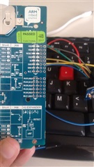
Note that to use pin 17, 19, 20, and 21 on the PCA10056 you will need to cut some solder bridges and do some soldering as these pins are not actually connected to the P24 header on the kit by default (as is described in the image you have posted): Solder bridge configuration.
Hi MartinBL,
I amnot using PCA 10056.I am using PCA10040.can you share link of updated git hub example
thank you
Hi MartinBL,
I amnot using PCA 10056.I am using PCA10040.can you share link of updated git hub example
thank you
Then why did you post an image of the pin documentation for the PCA10056? The PCA10040 version on github should work out of the box. Have you tried the example with the default pins? You can't use pin 21 on the kit. Refer to the silkscreen below the kit to see why.
Yes,I cant use pin 21.
which pins of nrf52 dk do i need to use defualt pins 4,28,3,29 given in nrf_drv_mpu_spi.c ?
yes,I tried with default pins.
i didnot get accel values.I even tried to print on jlink RTT viewer by giving some logs in main() function .but nothing printed on jlink RTT.
hi ,
Default pins specified in nrf_drv_mpu_spi.c are pin 4,28,3,29.do I need to connect these 4 wires as shown in image
Hi,
Can you try download a fresh copy of the examples from github and try again: Please use the pin described in the example:
In nrf_drv_mpu_spi.c:
#define MPU_SPI_MISO_PIN 28 // MPU SDO. 'AD0' on MPU breakout board silk screen #define MPU_SPI_MOSI_PIN 4 // MPU SDI. 'SDA' on MPU breakout board silk screen #define MPU_SPI_SCL_PIN 3 // MPU SCLK. 'SCL' on MPU breakout board silk screen #define MPU_SPI_CS_PIN 29 // MPU nCS. 'NCS' on MPU breakout board silk screen
In main.c
#define MPU_MPU_INT_PIN 30
And remember to program the Softdevice in addition to the application.
It should work straight out of the box. If it doesn't there must be something wrong with your kit, sensor, or wiring.