This post is older than 2 years and might not be relevant anymore
More Info: Consider searching for newer posts

AAA voltage measurement

Hi,

I'm using a NRF52832. I'm looking to measure the battery voltage. I'm using 2XAAA cells in serie (voltage range between 2V and 3V).

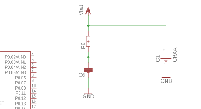
Below is the configuration to measure the voltage (To simplify the example, I have voluntarily removed protections on the battery connection). 

Regarding the internal characteristics of the ADC on NRF52, what is the best value for R6 and C6 to avoid any issue with acquisition time / impedance ...? Could you confirm that the leakage would be very low (input impedance >1M Ohms on the ADC input)?

EDIT  : In my real use case, the NRF is not directly powered by the batteries but by a boost circuit (3V). 

Thank you

Parents
  • I assume you are actually powering the nRF with the 2xAAA batteries, if so there is no reason to provide an external connection to the batteries.  You can configure the SAADC to measure the nRF VDD via its register settings. It has internal hardware connections to VDD to facilitate this.

  • Thank you for your reply.

    I have over simplified my example regarding the real schematic. In my case, the nRF is powered by a boost circuit (3V) so I need hardware to do the battery voltage measurement. 

  • That just begs more questions.  Why do you need to boost anything?

    The nRF will operate from 1.8V to 3.6V on it's internal DC/DC.

  • If it's a gpio issue that forces you to run the nRF at 3v constant, then I suggest you take a close look at your peripheral IC's.  Most devices have a wide operating range. As long as all the peripherals use the same VDD the comms voltages will all be the same.

  • It's because I'm using other external devices like buzzer etc...I'm also using some specific sensors which are not working below 3V. 

  • Since Vbat should never be greater than VDD, you can just hook it up directly. Realistically Vbat needs to be within Vthreshold of VDD.  Basically you want to make sure the top fet in the CMOS doesn't turn on by providing an input voltage greater than VDD + Vthreshold. Normally this shows in spec's as VDD + 0.3V. for max.

    The SAADC is a switched capacitive input that successive approximation is done against.  When it is not sampling you are looking at a turned off fet. So very, very high impedance.

    Nordic normally specify 1Mohm, but often state is is significantly larger than that. Since you don't need the resistor then you don't need the cap.  Just hook it up directly.

    If you are worried about having Ain sitting directly on Vbat which customers touch when swapping out the batteries then follow the guidelines for LiPo measurement but just lose the bottom half of the voltage divider so you won't have any leakage.

    The input cap on the SAADC is very small ( a few pF) so without giving it much thought you could just choose 100kohm and 1nF. The SAADC and the 1nF do coulomb sharing.  So you can always fix the acquisition time to compensate.

    LiPo guide if you wish to look at it: devzone.nordicsemi.com/.../measuring-lithium-battery-voltage-with-nrf52

  • Here is the bit from the spec on reference selection and input voltage range:

    37.8 Reference
    The ADC can use two different references, controlled in the REFSEL field of the CH[n].CONFIG register.
    These are:
    • Internal reference
    • VDD as reference
    The internal reference results in an input range of ±0.6 V on the ADC core. VDD as reference results in an
    input range of ±VDD/4 on the ADC core. The gain block can be used to change the effective input range of
    the ADC.
    Input range = (+- 0.6 V or +-VDD/4)/Gain
    For example, choosing VDD as reference, single ended input (grounded negative input), and a gain of 1/4
    the input range will be:
    Input range = (VDD/4)/(1/4) = VDD
    With internal reference, single ended input (grounded negative input), and a gain of 1/6 the input range will
    be:
    Input range = (0.6 V)/(1/6) = 3.6 V
    The AIN0-AIN7 inputs cannot exceed VDD, or be lower than VSS.

Reply
  • Here is the bit from the spec on reference selection and input voltage range:

    37.8 Reference
    The ADC can use two different references, controlled in the REFSEL field of the CH[n].CONFIG register.
    These are:
    • Internal reference
    • VDD as reference
    The internal reference results in an input range of ±0.6 V on the ADC core. VDD as reference results in an
    input range of ±VDD/4 on the ADC core. The gain block can be used to change the effective input range of
    the ADC.
    Input range = (+- 0.6 V or +-VDD/4)/Gain
    For example, choosing VDD as reference, single ended input (grounded negative input), and a gain of 1/4
    the input range will be:
    Input range = (VDD/4)/(1/4) = VDD
    With internal reference, single ended input (grounded negative input), and a gain of 1/6 the input range will
    be:
    Input range = (0.6 V)/(1/6) = 3.6 V
    The AIN0-AIN7 inputs cannot exceed VDD, or be lower than VSS.

Children
No Data
Related