This post is older than 2 years and might not be relevant anymore
More Info: Consider searching for newer posts

External Programming with nRF5-DK P20

Hello everyone,

i know that there are many similiar questions on the DevZone but i am not able to get it work and i dont uderstand it yet. I want to flash a custom board.

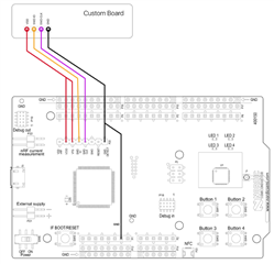
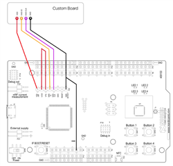
I connect the nRF5-DK to the custom board as the following:

  • Custom Board powered with 3V coin cell
  • P20 Pin 2 VDD to VDD of custom board
  • P20 Pin 4 SWDIO to SWDIO of custom board
  • P20 Pin 5 SWD CLK to SWD CLK of custom board
  • P20 Pin 8 GND DETECT to GND of custom board. Also tried to use GND of P13  or both. As shown in other questions.

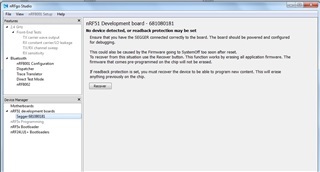
When i use nRFgo Studio , always the internal nRF is flashed. I know the priority is as follows:

  • If target power (3V3) is detected on P19 (= some board is attached and powered) it uses that as target, nothing is sent to P20 or internal nRF52 chip.
  • If nothing detected on P19 but target power is visible on P20 then it targets this interface (not the internal nRF52 chip).
  • If P19 and P20 seems to be unpowered then SEGGER J-Link OB target's built-in nRF52 chip on the board

I applied 3,0 to 3,3 V to P20.2 and P20.8 (just the voltage, no custom coard) and still the internal chip was succesfully flashed. In that case expected something like a failure. What would you expect here?

On Software side i start with the blank blinky from the sdk. I modified pca10040.h to be suitable with my custom board. One LED is common for both (nRF-DK and custom) so that i know which chip was used.

Do you have any suggestions or guaidance? I want to use P20 as i do not have the connectors for P19 yet.

Edit: I did the test with the external voltage because i would like to indicate, if my custom board has a failure. (Eg Board is powered up, but faulty --> error while flashing)

Kind regards

DanKa

  • Hi,


    You'll need to apply voltage to the "VTG" pin on header P20 (pin 3).

    You can do this by shorting P20, pin 2 and 3, as this will force the segger IC to externally program on P20.


    You can then power your external board from "VDD_NRF" (P20, pin 1), just remember to remove the battery first.


    Could you try this and see if you have any luck?


    Best regards,

    Håkon

  • I am not sure if i understand you correctly:

    • P20 Pin 2 VDD and Pin 3 to VDD of custom board OR just shorting Pin 2 and Pin

    I understand you as:

    • Custom Board powered by VDD_NRF (P20, pin 1), no battery.
    • P20 Pin 2 VDD and Pin 3 VTG shorted, no Connection to custom board
    • P20 Pin 4 SWDIO to SWDIO of custom board
    • P20 Pin 5 SWD CLK to SWD CLK of custom board
    • P20 Pin 8 GND DETECT shorted with GND (to supply) to GND of custom board.

    Is that correct?

    Edit:

    I did it as i mentioned above. With this setup i do not detect the inernal nRF5 anymore (as wanted), but if click on the SEGGER in nRFgo Studio, the nRF-DK resets. nRfgo Studio seems to Output a report or something but it disappears immediately. Something with no device detection...Is there a log or something? i can't read it in nRFgo Studio directly.

    Kind regards

  • That is strange.

    Have you tried using nrfjprog (from cmd, "nrfjprog --program <hex> --sectorerase"), or using J-Link Commander from the segger utils?


    Cheers,

    Håkon

  • Hello Hakon,

    i captured a screenshot from nRFgo Studio which i attached

     As i said, the nRF-DK seems to reset. So the Output disappears. Using nrfjprog --program is basically the same message:

    ERROR: Cannot connect to any nRF device. Please make sure the device is
    ERROR: connected to the debugger and supplied.

    Using nrfjprog --recover, it takes a while and then this is displayed:

    Recovering device. This operation might take 30s.
    ERROR: Cannot connect to any nRF device. Please make sure a device is
    ERROR: connected to the debugger and supplied.

    In Addition, the Dialog from J-Link commander. I tried with different Speed.

    Type "connect" to establish a target connection, '?' for help
    J-Link>connect
    Please specify device / core. <Default>: NRF51822_XXAA
    Type '?' for selection dialog
    Device>?
    Please specify target interface:
      J) JTAG (Default)
      S) SWD
    TIF>S
    Specify target interface speed [kHz]. <Default>: 4000 kHz
    Speed>100
    Device "NRF52832_XXAA" selected.

    ****** Error: Communication timed out: Requested 20 bytes, received 0 bytes !
    Could not read hardware status!
    Can not connect to target.

    I tried with different DKs and multiple custom boards. I measure 2.85V on VDD_nRF of custom board, P20.2 and  P20.3. I tried with these wirings, with and without external supply.


     I made one board, for nRF51822 and another for nRF52810/52832. Schematics and Layout are close to the ref layout. SWDCLK is not pulled down:

    nRF51822_Pi_Meander.sch (1).pdfnRF52810_Pi_Meander.sch.pdf

    Any help how to debug this is appreciated.

    Thank you and kind regards

    DanKa

     Update:

    It seems that there was a soldering problem. I am able to program the blinky Project. Further testing in Progress.

    The wiring of the second picture worked for me - no battery connected.

  • Good to hear that you found the source of the issue!


    Cheers,

    Håkon

Related