Hello everyone,
i know that there are many similiar questions on the DevZone but i am not able to get it work and i dont uderstand it yet. I want to flash a custom board.
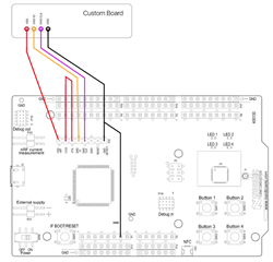
I connect the nRF5-DK to the custom board as the following:
- Custom Board powered with 3V coin cell
- P20 Pin 2 VDD to VDD of custom board
- P20 Pin 4 SWDIO to SWDIO of custom board
- P20 Pin 5 SWD CLK to SWD CLK of custom board
- P20 Pin 8 GND DETECT to GND of custom board. Also tried to use GND of P13 or both. As shown in other questions.
When i use nRFgo Studio , always the internal nRF is flashed. I know the priority is as follows:
- If target power (3V3) is detected on P19 (= some board is attached and powered) it uses that as target, nothing is sent to P20 or internal nRF52 chip.
- If nothing detected on P19 but target power is visible on P20 then it targets this interface (not the internal nRF52 chip).
- If P19 and P20 seems to be unpowered then SEGGER J-Link OB target's built-in nRF52 chip on the board
I applied 3,0 to 3,3 V to P20.2 and P20.8 (just the voltage, no custom coard) and still the internal chip was succesfully flashed. In that case expected something like a failure. What would you expect here?
On Software side i start with the blank blinky from the sdk. I modified pca10040.h to be suitable with my custom board. One LED is common for both (nRF-DK and custom) so that i know which chip was used.
Do you have any suggestions or guaidance? I want to use P20 as i do not have the connectors for P19 yet.
Edit: I did the test with the external voltage because i would like to indicate, if my custom board has a failure. (Eg Board is powered up, but faulty --> error while flashing)
Kind regards
DanKa


