This post is older than 2 years and might not be relevant anymore
More Info: Consider searching for newer posts

External Programming with nRF5-DK P20

Hello everyone,

i know that there are many similiar questions on the DevZone but i am not able to get it work and i dont uderstand it yet. I want to flash a custom board.

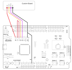
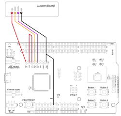
I connect the nRF5-DK to the custom board as the following:

  • Custom Board powered with 3V coin cell
  • P20 Pin 2 VDD to VDD of custom board
  • P20 Pin 4 SWDIO to SWDIO of custom board
  • P20 Pin 5 SWD CLK to SWD CLK of custom board
  • P20 Pin 8 GND DETECT to GND of custom board. Also tried to use GND of P13  or both. As shown in other questions.

When i use nRFgo Studio , always the internal nRF is flashed. I know the priority is as follows:

  • If target power (3V3) is detected on P19 (= some board is attached and powered) it uses that as target, nothing is sent to P20 or internal nRF52 chip.
  • If nothing detected on P19 but target power is visible on P20 then it targets this interface (not the internal nRF52 chip).
  • If P19 and P20 seems to be unpowered then SEGGER J-Link OB target's built-in nRF52 chip on the board

I applied 3,0 to 3,3 V to P20.2 and P20.8 (just the voltage, no custom coard) and still the internal chip was succesfully flashed. In that case expected something like a failure. What would you expect here?

On Software side i start with the blank blinky from the sdk. I modified pca10040.h to be suitable with my custom board. One LED is common for both (nRF-DK and custom) so that i know which chip was used.

Do you have any suggestions or guaidance? I want to use P20 as i do not have the connectors for P19 yet.

Edit: I did the test with the external voltage because i would like to indicate, if my custom board has a failure. (Eg Board is powered up, but faulty --> error while flashing)

Kind regards

DanKa

Parents
  • Hello Hakon,

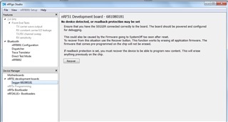
    i captured a screenshot from nRFgo Studio which i attached

     As i said, the nRF-DK seems to reset. So the Output disappears. Using nrfjprog --program is basically the same message:

    ERROR: Cannot connect to any nRF device. Please make sure the device is
    ERROR: connected to the debugger and supplied.

    Using nrfjprog --recover, it takes a while and then this is displayed:

    Recovering device. This operation might take 30s.
    ERROR: Cannot connect to any nRF device. Please make sure a device is
    ERROR: connected to the debugger and supplied.

    In Addition, the Dialog from J-Link commander. I tried with different Speed.

    Type "connect" to establish a target connection, '?' for help
    J-Link>connect
    Please specify device / core. <Default>: NRF51822_XXAA
    Type '?' for selection dialog
    Device>?
    Please specify target interface:
      J) JTAG (Default)
      S) SWD
    TIF>S
    Specify target interface speed [kHz]. <Default>: 4000 kHz
    Speed>100
    Device "NRF52832_XXAA" selected.

    ****** Error: Communication timed out: Requested 20 bytes, received 0 bytes !
    Could not read hardware status!
    Can not connect to target.

    I tried with different DKs and multiple custom boards. I measure 2.85V on VDD_nRF of custom board, P20.2 and  P20.3. I tried with these wirings, with and without external supply.


     I made one board, for nRF51822 and another for nRF52810/52832. Schematics and Layout are close to the ref layout. SWDCLK is not pulled down:

    nRF51822_Pi_Meander.sch (1).pdfnRF52810_Pi_Meander.sch.pdf

    Any help how to debug this is appreciated.

    Thank you and kind regards

    DanKa

     Update:

    It seems that there was a soldering problem. I am able to program the blinky Project. Further testing in Progress.

    The wiring of the second picture worked for me - no battery connected.

  • I set up the wire according to your schematic on the right, and had the same issue in nrfgo studio, no device detected. Can you tell me how you make it work with a little bit more details?

    Appreciate it. 

  • Hi,

    I can confirm that this schematic works
    (physically wired P20:GND Detect --> P1:GND and then P1:GND -->Custom Board:GND) :

    Unfortunately, I have no further details to add. As I mentioned in my post, there was soldering issue. I was able to use all functions of the device after resoldering.
    Have you tried nrfjprog and J-Link commander?
Reply Children
Related