This post is older than 2 years and might not be relevant anymore
More Info: Consider searching for newer posts

Current consumption rtc-> ppi ->gpiote on nrf52

This thread discusses the nrf51  devzone.nordicsemi.com/.../current-consumption-when-using-rtc-ppi-and-gpiote  It says that the PPI (for nrf51 chip revisions up to rev 3) keeps the 16mhz clock on, and that Nordic doesn't recommend this combination for low power.  Is that still true for the nrf52?

I am doing the same thing as that thread: using the rtc to generate an event, which the ppi connects to a gpiote out task, which toggles an out pin.  (all without cpu waking.)   If someone has not already measured the current consumption for this combination, then I will just go back to using an ISR ( rtc generates an interrupt, and the ISR toggles the pin using the GPIO device.  Current consumption is only the current of the sleeping mcu and rtc.)

The product specs don't seem to have an electrical specification for the PPI, nor a value for the current of a GPIOTE out channel.

Parents
  • Hey butch,

    I've made a small application demonstrating PPI vs CPU interrupts. rtc_ppi_gpiote.zip

    You have to compile the application with the definition USE_PPI to use PPI+GPIOTE.

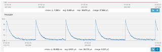
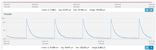
    I've also compared the current consumption between the two:
    With PPI:

    With CPU interrupt:


    As you can see the difference is dramatic. The RTC interrupt will also be at the mercy of it's execution/preemption priority, whereas the PPI system is completely independent from the CPU state. 

    Cheers,

    Håkon.

  • Thank you very much. (I would test it myself if I had a scope.)

    However, your graphs do not show the minimum. The minimum would show the current during sleep. It might be that the minimum for PPI case is more than the minimum for interrupt case. (The resolution of the graphs does not let me compare the exact minimums.)

    In other words, you are triggering the timer every 10ms, whereas I am interested in triggering the timer every ten seconds or so. In my case, the long tail of the curve at a lower minimum might mean that the average was much less (despite the high max current for the peak.)

    My actual application is an "I'm alive" LED, that flashes very briefly (the minimum that the human eye can see) every ten seconds or so. I want to use the PPI to toggle the LED off. While the LED on, the current of the PPI is insignificant, since the current of the LED is much more. While the LED is off, the current of the PPI+GPIOTE might be significant (relative to say they 4 (?) uSec sleeping current of the CPU + LFXO + RTC.) The question is not only what is the current of PPI+GPIOTE but is it really the current of the PPI+GPIOTE+HFRC (emphasis on HFRC, as it seems to have been in early revisions of the nrf51?)

    Whereas your illustrated use case is more of "PWM" or "signal", i.e. with much higher frequency. In that case, yes there are clear advantages to using the PPI and GPIOTE.

    And maybe my question is moot, if my implementation disables the PPI and GPIOTE when the LED is turned off. But that implementation might require an interrupt anyway? Maybe the implementation can configure the PPI so that the rtc event not only triggers the gpiote task to toggle the LED but also triggers a fork task that disables one of the PPI's own channel groups via the task NRF_PPI->TASK_CHG[0].DIS. One needs to know the specification for current of the enabled PPI and GPIOTE to know whether such a design is beneficial for a given frequency of operation.

    I very much admire the design of the PPI and GPIOTE as a hw implementation of the sw concept of signals (in the Qt terminology, signals and slots.)

Reply
  • Thank you very much. (I would test it myself if I had a scope.)

    However, your graphs do not show the minimum. The minimum would show the current during sleep. It might be that the minimum for PPI case is more than the minimum for interrupt case. (The resolution of the graphs does not let me compare the exact minimums.)

    In other words, you are triggering the timer every 10ms, whereas I am interested in triggering the timer every ten seconds or so. In my case, the long tail of the curve at a lower minimum might mean that the average was much less (despite the high max current for the peak.)

    My actual application is an "I'm alive" LED, that flashes very briefly (the minimum that the human eye can see) every ten seconds or so. I want to use the PPI to toggle the LED off. While the LED on, the current of the PPI is insignificant, since the current of the LED is much more. While the LED is off, the current of the PPI+GPIOTE might be significant (relative to say they 4 (?) uSec sleeping current of the CPU + LFXO + RTC.) The question is not only what is the current of PPI+GPIOTE but is it really the current of the PPI+GPIOTE+HFRC (emphasis on HFRC, as it seems to have been in early revisions of the nrf51?)

    Whereas your illustrated use case is more of "PWM" or "signal", i.e. with much higher frequency. In that case, yes there are clear advantages to using the PPI and GPIOTE.

    And maybe my question is moot, if my implementation disables the PPI and GPIOTE when the LED is turned off. But that implementation might require an interrupt anyway? Maybe the implementation can configure the PPI so that the rtc event not only triggers the gpiote task to toggle the LED but also triggers a fork task that disables one of the PPI's own channel groups via the task NRF_PPI->TASK_CHG[0].DIS. One needs to know the specification for current of the enabled PPI and GPIOTE to know whether such a design is beneficial for a given frequency of operation.

    I very much admire the design of the PPI and GPIOTE as a hw implementation of the sw concept of signals (in the Qt terminology, signals and slots.)

Children
Related