Hello!
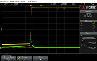
We have nRF52832 chip on our product and we have some problem with one of its IOs.. We configured P0.16 as RX of UART, And when we run it we see this behavior of this IO:

Here we see that with rising of VCC (yellow signal) IO (green) rising to almost 1V when it supposed to still at 0V. Important note: we disable and enable VCC fast here so we see that before rising of VCC it don't have 0V. This behaviour is very problematic to our system. Because we have power supply sensitive sensor that connected to this UART. This spike of voltage damage sensor that connected to this IO.
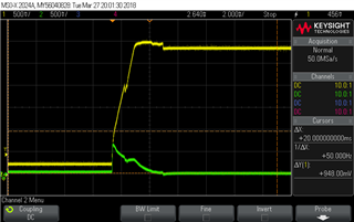
We tried to load to evaluation board same version of SW on nRF52832 and we got next result:

We see that also here we have the problematic spike.
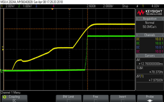
When we erased the evaluation board - we got the same result.
Is this IO known as problematic?
Thank you


