Beware that this post is related to an SDK in maintenance mode
More Info: Consider nRF Connect SDK for new designs
This post is older than 2 years and might not be relevant anymore
More Info: Consider searching for newer posts

Interaction between GPIOTE pin and UART RTS

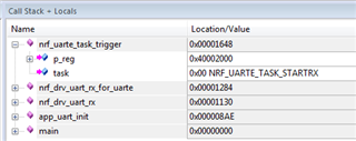
I have the UART configured using the standard boiler plate code, with flow control enabled, where the RTS output is assigned pin 5.

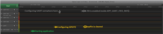
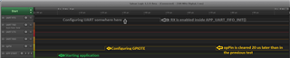
 I have defined a GPIOTE pin 25 as an output, with its initial state defined as Hi. I then set this output low using nrf_drv_gpiote_out_clear(opPin ); sure enough opPin goes low, however so does RTS.

This is 100% repeatable.

Any ideas?

Parents
  • Hi,

    That's pretty strange. 

    Do you mind posting the code showing how you configure pin 25 as an output, or preferably the whole code? That is the only thing you added to the SDK example right?

    What SDK version do you use? And what is the complete serial number on top of your nRF5 IC?

  • Using on sdk_13.0.0_04a0bfd Based on the UART example.

    Hardware: V1.00

    S/N: 682336494

    I configure the pin 25 thus:

    #define opPin	25
    void io_init( void ) {
        ret_code_t err_code;
        err_code = nrf_drv_gpiote_init();
        APP_ERROR_CHECK(err_code);
    
        /**
         * Output
         */
    	// Where the true specifies the initial state of the O/P line so in  this case Hi
    	nrf_drv_gpiote_out_config_t out_config = GPIOTE_CONFIG_OUT_SIMPLE( true );
    	err_code = nrf_drv_gpiote_out_init(opPin, &out_config);
    	APP_ERROR_CHECK(err_code);
    }
    

    configuring the UART (you will notice the desperate attempts to keep RTS Hi !! even this generates a 1.98us low during the execution of APP_UART_FIFO_INIT):

    static void uart_init() {
        uint32_t err_code;
        const app_uart_comm_params_t comm_params =
          {
              RX_PIN_NUMBER,
              TX_PIN_NUMBER,
              RTS_PIN_NUMBER,
              CTS_PIN_NUMBER,
    		  APP_UART_FLOW_CONTROL_ENABLED,//APP_UART_FLOW_CONTROL_DISABLED,//
              false,
    		  UART_BAUDRATE_BAUDRATE_Baud4800 //UART_BAUDRATE_BAUDRATE_Baud115200
          };
    
        NRF_UART0->TASKS_STOPRX = 1;
        APP_UART_FIFO_INIT(&comm_params,
                             UART_RX_BUF_SIZE,
                             UART_TX_BUF_SIZE,
    						 uart_error_handle,
                             APP_IRQ_PRIORITY_LOWEST,
                             err_code);
        NRF_UART0->TASKS_STOPRX = 1;
        APP_ERROR_CHECK(err_code);
    }

    and then to take opPin Low:

    nrf_drv_gpiote_out_clear( opPin );

    The weird thing is I have also see the same effect caused by the execution of this line:

    SEGGER_RTT_WriteString(0, "Exectuing UART Test\n");

    which is called after the initialisation of UART and IO as seen below in main which a bit of a mess, however if you step through from the start, I see RTS go Low when the opPin is cleared, and No opPin is not connected to RTS!

    int main(void)
    {
    	io_init();
        uart_init();
        NRF_UART0->TASKS_STOPRX = 1;
        nrf_drv_gpiote_out_clear( opPin );
        NRF_UART0->TASKS_STOPRX = 1;
        //SEGGER_RTT_WriteString(0, "Exectuing UART Test\n"); // Print message to RTT to the application flow
        //log_init();
    
        //printf("uart_init\r\n");
        //SEGGER_RTT_printf(0, "uart_init\r\n"); // Print service UUID should match definition BLE_UUID_OUR_SERVICE
        //bsp_board_leds_init();
    
        //SEGGER_RTT_WriteString(0,"io_init\r\n");
        //app_uart_flush();
    
        nrf_drv_gpiote_out_clear( opPin );
        NRF_UART0->TASKS_STOPRX = 1;
        //while( !configComplete ){}
    
        while (true) {
        	// do nothing
        }
    }

    I am suspicious of my sdk_config.h

    3755.sdk_config.h

  • Hi,

    I have done some more debugging and I have a question for you: Are you sure this is related to the GPIO and/or the RTT? What happens if you don't do anything after initializing the UART?

    In an attempt to narrow it it down I got as far as this:

    #define OUT_PIN	25
    
    int main(void)
    {    
        NRF_UARTE0->PSEL.RTS = RTS_PIN_NUMBER;
        NRF_UARTE0->ENABLE = 8;    
        NRF_UARTE0->TASKS_STARTRX = 1;
        
        while (true) {
        	
        }
    }

    As you can see it wasn't necessary to toggle any GPIO to make the RTS go low. It was only necessary to start the RX and this also happens inside APP_UART_FIFO_INIT().

    So it might be that this is just expected behaviour. 

  • Thanks for pursuing this.

    I am not sure which component is misbehaving GPIO and/or the RTT. [context] I decided to use a completely unrelated custom (as I thought) IO line (Pin 24 (Pin 25 appeared to have some decoupling)) to control the CTS line on my peripheral as I couldn't get the Nordic RTS line to change and block incoming data. The inability to block incoming data resulted in overrun errors.

    [observation] It was while changing my custom GPIO line, stepping through the code, that I saw the Nordic RTS change state. My custom GPIO line and the Nordic RTS line were/are completely disconnected both physically (not connected electrically) and code. I wouldn't consider this expected behaviour which is why I hi-lighted the issue.

    I have recently made progress using the custom GPIO line as I can change its state (exactly when needed) relative to reseting the peripheral on another GPIO line. I would have preferred not to have used this approach and to have pursued a the conventional configuration.

  • Hi,

    I have debugged some more and I think the problem is that the RX task is enabled inside APP_UART_FIFO_INIT(), as I mentioned earlier. Here is the call stack with the path to the instruction.

    After RX is enabled, the UART feels ready to receive and hence activates the RTS signal. I don't think it is related to neither RTT nor any GPIO actions. At least I'm not able to reproduce that. The enabling of RX is embedded quite deep into the app_uart library and I couldn't find a way to cheat it. Hence I think you need to keep doing what you describe above, or drop the app_uart library and use the UART drivers directly.

  • Martin thanks for pursuing this further. I would like to use your (the Nordic) RTS, however given that it changes state when I change the state of an GPIOTE line then I think the likely hood is low - this cannot be correct and must be a bug.

    Currently don't have time to investigate using the UART drivers directly, however it would engender greater understanding so would be an aspiration. Is there any example code and or documentation taking the read from an abstract level down the meet the driver?

  • Hi,

    Maybe we are just talking past each other here, but anyway I did some more tests:

    Here is the code I used. It is the same code as you posted above. I just removed unnecessary lines for better readability:

    #define MAX_TEST_DATA_BYTES     (15U)                /**< max number of test bytes to be used for tx and rx. */
    #define UART_TX_BUF_SIZE 256                         /**< UART TX buffer size. */
    #define UART_RX_BUF_SIZE 256                         /**< UART RX buffer size. */
    
    void uart_error_handle(app_uart_evt_t * p_event)
    {
        if (p_event->evt_type == APP_UART_COMMUNICATION_ERROR)
        {
            APP_ERROR_HANDLER(p_event->data.error_communication);
        }
        else if (p_event->evt_type == APP_UART_FIFO_ERROR)
        {
            APP_ERROR_HANDLER(p_event->data.error_code);
        }
    }
    
    
    #define opPin	25
    void io_init( void ) {
        ret_code_t err_code;
        err_code = nrf_drv_gpiote_init();
        APP_ERROR_CHECK(err_code);
    
        /**
         * Output
         */
    	// Where the true specifies the initial state of the O/P line so in  this case Hi
    	nrf_drv_gpiote_out_config_t out_config = GPIOTE_CONFIG_OUT_SIMPLE( true );
    	err_code = nrf_drv_gpiote_out_init(opPin, &out_config);
    	APP_ERROR_CHECK(err_code);
    }
    
    static void uart_init() {
        uint32_t err_code;
        const app_uart_comm_params_t comm_params =
          {
              RX_PIN_NUMBER,
              TX_PIN_NUMBER,
              RTS_PIN_NUMBER,
              CTS_PIN_NUMBER,
    		  APP_UART_FLOW_CONTROL_ENABLED,//APP_UART_FLOW_CONTROL_DISABLED,//
              false,
    		  UART_BAUDRATE_BAUDRATE_Baud4800 //UART_BAUDRATE_BAUDRATE_Baud115200
          };
    
        //NRF_UART0->TASKS_STOPRX = 1;
        APP_UART_FIFO_INIT(&comm_params,
                             UART_RX_BUF_SIZE,
                             UART_TX_BUF_SIZE,
    						 uart_error_handle,
                             APP_IRQ_PRIORITY_LOWEST,
                             err_code);
        //NRF_UART0->TASKS_STOPRX = 1;
        APP_ERROR_CHECK(err_code);
    }
    
    
    int main(void)
    {
        // Mark start of application
        nrf_gpio_cfg_output(26);
        nrf_gpio_pin_set(26);
        
    	io_init();
        uart_init();
        //nrf_delay_us(10);
        nrf_drv_gpiote_out_clear( opPin );
        //SEGGER_RTT_WriteString(0,"io_init\r\n");
    
        while (true) {
        	// do nothing
        }
    }

    Here are the outputs of the UART lines, the opPin, and a GPIO that I used to trigger the logic analyzer at the beginning of main:

    In the second test I changed the code in main a bit:

    io_init();
    uart_init();
    nrf_delay_us(20); // <- Make a 20 us delay between UART init and clearing the GPIO
    nrf_drv_gpiote_out_clear( opPin );
    //SEGGER_RTT_WriteString(0,"io_init\r\n");

    Notice that I added a 20 us delay between the UART init and the clearing of the GPIO. This is the logic output:

    In the final test I didn't do anything at all after initializing the UART:

    io_init();
    uart_init();
    //nrf_delay_us(20); // <- Make a 20 us delay between UART init and clearing the GPIO
    //nrf_drv_gpiote_out_clear( opPin );
    //SEGGER_RTT_WriteString(0,"io_init\r\n");

    The RTS still goes low:

    This proves that toggling the GPIOTE has nothing to do with the RTS line going low. It goes low because RX is enabled inside APP_UART_FIFO_INIT() and because at that point the UART is ready to receive. So it is not a HW bug that somehow mysteriously connects the RTS signal to the GPIOTE pin or RTT. In my opinion it is not a SW bug either, because this behaviour doesn't violate the UART specification, so to speak. The UART is ready to receive and hence the RTS should go low. 

    I don't think there are any ready made examples showcasing only the UART driver, but the driver is documented here, and you can pretty much just copy-paste the code presented there.

Reply
  • Hi,

    Maybe we are just talking past each other here, but anyway I did some more tests:

    Here is the code I used. It is the same code as you posted above. I just removed unnecessary lines for better readability:

    #define MAX_TEST_DATA_BYTES     (15U)                /**< max number of test bytes to be used for tx and rx. */
    #define UART_TX_BUF_SIZE 256                         /**< UART TX buffer size. */
    #define UART_RX_BUF_SIZE 256                         /**< UART RX buffer size. */
    
    void uart_error_handle(app_uart_evt_t * p_event)
    {
        if (p_event->evt_type == APP_UART_COMMUNICATION_ERROR)
        {
            APP_ERROR_HANDLER(p_event->data.error_communication);
        }
        else if (p_event->evt_type == APP_UART_FIFO_ERROR)
        {
            APP_ERROR_HANDLER(p_event->data.error_code);
        }
    }
    
    
    #define opPin	25
    void io_init( void ) {
        ret_code_t err_code;
        err_code = nrf_drv_gpiote_init();
        APP_ERROR_CHECK(err_code);
    
        /**
         * Output
         */
    	// Where the true specifies the initial state of the O/P line so in  this case Hi
    	nrf_drv_gpiote_out_config_t out_config = GPIOTE_CONFIG_OUT_SIMPLE( true );
    	err_code = nrf_drv_gpiote_out_init(opPin, &out_config);
    	APP_ERROR_CHECK(err_code);
    }
    
    static void uart_init() {
        uint32_t err_code;
        const app_uart_comm_params_t comm_params =
          {
              RX_PIN_NUMBER,
              TX_PIN_NUMBER,
              RTS_PIN_NUMBER,
              CTS_PIN_NUMBER,
    		  APP_UART_FLOW_CONTROL_ENABLED,//APP_UART_FLOW_CONTROL_DISABLED,//
              false,
    		  UART_BAUDRATE_BAUDRATE_Baud4800 //UART_BAUDRATE_BAUDRATE_Baud115200
          };
    
        //NRF_UART0->TASKS_STOPRX = 1;
        APP_UART_FIFO_INIT(&comm_params,
                             UART_RX_BUF_SIZE,
                             UART_TX_BUF_SIZE,
    						 uart_error_handle,
                             APP_IRQ_PRIORITY_LOWEST,
                             err_code);
        //NRF_UART0->TASKS_STOPRX = 1;
        APP_ERROR_CHECK(err_code);
    }
    
    
    int main(void)
    {
        // Mark start of application
        nrf_gpio_cfg_output(26);
        nrf_gpio_pin_set(26);
        
    	io_init();
        uart_init();
        //nrf_delay_us(10);
        nrf_drv_gpiote_out_clear( opPin );
        //SEGGER_RTT_WriteString(0,"io_init\r\n");
    
        while (true) {
        	// do nothing
        }
    }

    Here are the outputs of the UART lines, the opPin, and a GPIO that I used to trigger the logic analyzer at the beginning of main:

    In the second test I changed the code in main a bit:

    io_init();
    uart_init();
    nrf_delay_us(20); // <- Make a 20 us delay between UART init and clearing the GPIO
    nrf_drv_gpiote_out_clear( opPin );
    //SEGGER_RTT_WriteString(0,"io_init\r\n");

    Notice that I added a 20 us delay between the UART init and the clearing of the GPIO. This is the logic output:

    In the final test I didn't do anything at all after initializing the UART:

    io_init();
    uart_init();
    //nrf_delay_us(20); // <- Make a 20 us delay between UART init and clearing the GPIO
    //nrf_drv_gpiote_out_clear( opPin );
    //SEGGER_RTT_WriteString(0,"io_init\r\n");

    The RTS still goes low:

    This proves that toggling the GPIOTE has nothing to do with the RTS line going low. It goes low because RX is enabled inside APP_UART_FIFO_INIT() and because at that point the UART is ready to receive. So it is not a HW bug that somehow mysteriously connects the RTS signal to the GPIOTE pin or RTT. In my opinion it is not a SW bug either, because this behaviour doesn't violate the UART specification, so to speak. The UART is ready to receive and hence the RTS should go low. 

    I don't think there are any ready made examples showcasing only the UART driver, but the driver is documented here, and you can pretty much just copy-paste the code presented there.

Children
  • Martin thanks for going the extra mile on this. I understand now and in the future will use debugger stepping with extra caution, sorry for being rather slow. However what I still find confusing is why RTS will still go low if you restore the second NRF_UART0->TASKS_STOPRX = 1; in uart_init() 

    On page 336 of nRF52832_PS_v1.4.pdf section 35.4 it states "If HW flow control is enabled the RTS signal will be deactivated when the receiver is stopped via the STOPRX task or when the UARTE is only able to receive four more bytes in its internal RX FIFO."

  • No worries. Happy to help.

    venerley said:
    However what I still find confusing is why RTS will still go low if you restore the second NRF_UART0->TASKS_STOPRX = 1; in uart_init() 

    Good question. I didn't take note of that. I think I figured it out though, and it is due to a "feature" in the UART driver.

    First, take note of this comment in the UARTE documentation:

    Important: If the ENDRX event has not already been generated when the UARTE receiver has come to a stop, which implies that all pending content in the RX FIFO has been moved to the RX buffer, the UARTE will generate the ENDRX event explicitly even though the RX buffer is not full. In this scenario the ENDRX event will be generated before the RXTO event is generated.

    So what happens is that when we stop the UART with TASKS_STOPRX, a subsequent EVENTS_ENDRX is still being generated anyway. This ENDRX event generates an interrupt that is handled by the UART driver. The driver then starts another RX by setting the TASKS_STARTRX task once again. In other words:

    1. You initialize the UART driver
    2. The driver starts UART RX
    3. The RTS goes low
    4. You stop UART RX with TASKS_STOPRX
    5. RTS goes high
    6. The UART HW generates an ENDRX event
    7. The UART driver responds to the ENDRX event
    8. The driver sees no reason to block RX so it starts UART RX and clears RTS once again.
Related