Beware that this post is related to an SDK in maintenance mode
More Info: Consider nRF Connect SDK for new designs
This post is older than 2 years and might not be relevant anymore
More Info: Consider searching for newer posts

Improving battery life: Use a capacitor ?

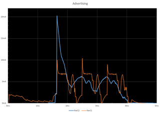
I was wondering if adding a capacitor in parallel with the coin cell battery would help with the battery life by smoothing out the peaks. The scenario shown in the chart is a BLE advertising event (every 1s). I first added a 10uF then also a 100uF capacitor in parallel and took a trace of the power profile. The two series shown is with a 10uF capacitor (orange line) and the other series with both 10uF+100uF capacitors (blue line). Looking at the charts, I have two questions:

1. For the 100uF series, why is there a large spike at the start of the advertising event ? I expected the larger capacitor to help smooth out the initial peak of the advertising event not make it worse. (there's a bit of CPU work before the main spike which is smoothed out but that should not deplete the capacitor). Instead, it looks like its charging at the same time and I suspect there needs to be some way to limit the draw of the capacitor. I tried adding in various resistors but that just converges to not having a capacitor in the first place.

2. It does not look like adding in the 100uF is helping at all, are there ways to make it help and not hurt or is it better to not have it ?

Update:

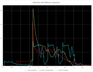
I am using the ppk with an external board thats using an nrf52832. The cap is 100µF ±20% 6.3V Ceramic Capacitor X5R 1210 (Kemet Part #: C1210C107M9PACTU). I re ran the tests using the power select from the ppk (reg) and also using an external supply (cr2450). I noticed some differences between using these two power sources (see chart below). The total charge used between using a cap and not using one seems to be about the same. I have aligned the charts manually so I cant say for sure what the exact alignment is between the scenarios but the added spike is still intriguing but somewhat less when using the battery power source. I had previously read the links provided in the responses below. 

Update 2:

I re ran the tests. For the first results I reported above I used the python version of the ppk UI, and now I tried the new desktop version and got very different results, much more inline with what one would intuitively think about it. So, by adding in the battery as the external supply and the new UI is what gave me intuitive results. I'm going to run it again on a power analyzer to make a final check :-)

Parents
  • Thanks for the links, I have been through those before. I have updated the question with some more details

  • Where did you put the cap on the PPK?

    You have to remember the PPK has a series resistance for current measurement.  You have to put the cap after the resistance just ahead of the nRF.

  • I've put it after the wires that come out of the 'External DUT' connectors of the ppk and before connecting to the external board. I have also soldered it onto the board like it would be for real, and both give very similar results. 

  • Well the physics don't lie and this is how you reduce power supply ripple.

    There are many things that can go wrong with your setup.  The PPK uses analog switches (ie, FETs) for range control and with switches, your scope settings which may be good or bad, lots of local grounds, and two types of power supplies a lot can go wrong.

    Also, your 1210 part is a poor choice for this design. As I said earlier we use an 0805 47uF along with distributed 0.1uF 0402's and 2.2uF 0402's.  Our 0805 parts have an SRF of over 1MHz and the 2.2uF's have an SRF of over 5MHz.  Your 1210 however has an SRF of only 575kHz. That's pretty low given the power amplifier in the nRF will come on in about 200nSec.  I encourage you to do the spice simulation but that is a rather slow part for a fast turn on device.  Plus since the modulation of BLE is 1MHz or 2MHz even the DC part of the modulation that shows up in the power supply will be well outside the range of your 1210 cap.

    Since what you really care about is reducing the ripple of a button cell you should test that and only that.  Get the PPK out of the equation and just test your DUT on a button cell then measure the voltage at the cell while under test.  With only one ground and one power source the results will be more clear and you will see the lowering of the ripple of the button cell due to its internal losses as you put more fast (ie, over 1MHz) capacitance on the system.

    I should add, if you really want to smooth out the ripple put a big inductor between the caps and battery.  This way you end up with a second order filter.  Again, I encourage you to simulate in spice, or equivalent, to see the results. You will have to do the calculations to come up with the appropriate uH's for the inductor and will need to balance ripple reduction with power loss from the DCR of the inductor.

  • Thanks for the reply, I'll try those enhancements and retest.

Reply Children
No Data
Related