Chevalier_nRF52840_schema_v0.pdf
Hello all,
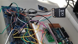
I have some troubles to initialize the micro SD card with my custom board.
I have used the nRF 52 DK to write a basic code and do some test. For micro card SD with the nRF 52 DK I have used this micro card SD reader
Here you can find the basic code. With my custom board the code can not do the initialization function. As the result disk_state = disk_initialize(0); is always true.
#include "nrf_drv_spi.h"
#include "app_util_platform.h"
#include "nrf_gpio.h"
#include "nrf_delay.h"
#include "boards.h"
#include "app_error.h"
#include <string.h>
#include "nrf_log.h"
#include "nrf_log_ctrl.h"
#include "nrf_log_default_backends.h"
#include "SEGGER_RTT.h"

#include "nrf.h"
#include "bsp.h"
#include "ff.h"
#include "diskio_blkdev.h"
#include "nrf_block_dev_sdc.h"
#include "app_sdcard.h"

#define SPI_INSTANCE  1 /**< SPI instance index. */
static const nrf_drv_spi_t spi = NRF_DRV_SPI_INSTANCE(SPI_INSTANCE); /**< SPI instance. */


#define FILE_NAME   "NORDIC.TXT"
#define TEST_STRING "SD card example."

#define SDC_SCK_PIN     42  ///< SDC serial clock (SCK) pin.
#define SDC_MOSI_PIN    36  ///< SDC serial data in (DI) pin.
#define SDC_MISO_PIN    45  ///< SDC serial data out (DO) pin.
#define SDC_CS_PIN      34  ///< SDC chip select (CS) pin. p1.02

/**
 * @brief  SDC block device definition
 * */
NRF_BLOCK_DEV_SDC_DEFINE(
        m_block_dev_sdc,
        NRF_BLOCK_DEV_SDC_CONFIG(
                SDC_SECTOR_SIZE,
                APP_SDCARD_CONFIG(SDC_MOSI_PIN, SDC_MISO_PIN, SDC_SCK_PIN, SDC_CS_PIN)
         ),
         NFR_BLOCK_DEV_INFO_CONFIG("PerfectStride", "SDC", "1.00")
);

/**
 * @brief Function for demonstrating FAFTS usage.
 */
void fatfs_example()
{
    static FATFS fs;
    static DIR dir;
    static FILINFO fno;
    static FIL file;

    uint32_t bytes_written;
    FRESULT ff_result;
    DSTATUS disk_state = STA_NOINIT;

    // Initialize FATFS disk I/O interface by providing the block device.
    static diskio_blkdev_t drives[] =
    {
            DISKIO_BLOCKDEV_CONFIG(NRF_BLOCKDEV_BASE_ADDR(m_block_dev_sdc, block_dev), NULL)
    };

    diskio_blockdev_register(drives, ARRAY_SIZE(drives));

    SEGGER_RTT_printf(0,"Initializing disk 0 (SDC)...");
    for (uint32_t retries = 3; retries && disk_state; --retries)
    {
        disk_state = disk_initialize(0);
    }
    if (disk_state)
    {
        SEGGER_RTT_printf(0,"Disk initialization failed.\n");
        return;
    }

    uint32_t blocks_per_mb = (1024uL * 1024uL) / m_block_dev_sdc.block_dev.p_ops->geometry(&m_block_dev_sdc.block_dev)->blk_size;
    uint32_t capacity = m_block_dev_sdc.block_dev.p_ops->geometry(&m_block_dev_sdc.block_dev)->blk_count / blocks_per_mb;
    SEGGER_RTT_printf(0,"Capacity: %d MB", capacity);

    SEGGER_RTT_printf(0,"Mounting volume...");
    ff_result = f_mount(&fs, "", 1);
    if (ff_result)
    {
        SEGGER_RTT_printf(0,"Mount failed.");
        return;
    }

    SEGGER_RTT_printf(0,"\r\n Listing directory: /");
    ff_result = f_opendir(&dir, "/");
    if (ff_result)
    {
        SEGGER_RTT_printf(0,"Directory listing failed!");
        return;
    }

//    ff_result = f_unlink(FILE_NAME); //LC: delete nordic file if exist before starting
    do
    {
        ff_result = f_readdir(&dir, &fno);
        if (ff_result != FR_OK)
        {
            SEGGER_RTT_printf(0,"Directory read failed.");
            return;
        }
        nrf_delay_ms(1000);
        if (fno.fname[0])
        {
            if (fno.fattrib & AM_DIR)
            {
                SEGGER_RTT_printf(0,"\n   <DIR>   %s",(uint32_t)fno.fname);
            }
            else
            {
                SEGGER_RTT_printf(0,"%9lu  %s", fno.fsize, (uint32_t)fno.fname);
            }
        }
    }
    while (fno.fname[0]);

    nrf_delay_ms(2000);
    SEGGER_RTT_printf(0,"\n \n");
    SEGGER_RTT_printf(0,"Writing to file %s ...   ", FILE_NAME);

    ff_result = f_open(&file, FILE_NAME, FA_READ | FA_WRITE | FA_OPEN_APPEND);
    if (ff_result != FR_OK)
    {
        SEGGER_RTT_printf(0,"Unable to open or create file: " FILE_NAME ".");
        return;
    }

    ff_result = f_write(&file, TEST_STRING, sizeof(TEST_STRING) - 1, (UINT *) &bytes_written);

    if (ff_result != FR_OK)
    {
        SEGGER_RTT_printf(0,"Write failed\r\n.");
    }
    else
    {
        SEGGER_RTT_printf(0,"%d bytes written.\n", bytes_written);
    }
SEGGER_RTT_printf(0,"before file close !");
    (void) f_close(&file);SEGGER_RTT_printf(0,"before out !");
    return;
}


void init_pins()
{
    SEGGER_RTT_printf(0, "\n \n-------- Fatfs CONFIG -------- \n");

    SEGGER_RTT_printf(0, "SDC_SCK_PIN   :\t %d \n", SDC_SCK_PIN);
    SEGGER_RTT_printf(0, "SDC_MOSI_PIN  :\t %d \n", SDC_MOSI_PIN);
    SEGGER_RTT_printf(0, "SDC_MISO_PIN  :\t %d \n", SDC_MISO_PIN);
    SEGGER_RTT_printf(0, "SDC_CS_PIN    :\t %d \n", SDC_CS_PIN);
    return;
}

void begin_message()
{
    SEGGER_RTT_printf(0, "\n\n\n \n\n\n -------------------------------------------------------- \n");
    SEGGER_RTT_printf(0, " Begin Perfect Stride program to read value from BMI160 sensor \n");
    SEGGER_RTT_printf(0, "\t linked with BMM150 sensor \n \n");
    return;
}


int main(void)
{
    begin_message();
    bsp_board_leds_init();

    init_pins();

    //LC ---- test
    fatfs_example();

    while (1)
    {
        bsp_board_led_invert(BSP_BOARD_LED_0);
        nrf_delay_ms(200);
    }
    //LC ---- end test
}
The file to configure the custom board is this one :
#include "boards.h"


#ifndef BOARD_CUSTOM_H
#define BOARD_CUSTOM_H

#ifdef __cplusplus
extern "C" {
#endif

#define LEDS_NUMBER    4

#define LED_1          NRF_GPIO_PIN_MAP(1,6)

#define LEDS_ACTIVE_STATE 0

#define LEDS_LIST { LED_1}

#define LEDS_INV_MASK  LEDS_MASK

#define BSP_LED_0      13
#define BSP_LED_1      14
#define BSP_LED_2      15
#define BSP_LED_3      16

#define BUTTONS_NUMBER 4

#define BUTTON_1       11
#define BUTTON_2       12
#define BUTTON_3       24
#define BUTTON_4       25
#define BUTTON_PULL    NRF_GPIO_PIN_PULLUP

#define BUTTONS_ACTIVE_STATE 0

#define BUTTONS_LIST { BUTTON_1, BUTTON_2, BUTTON_3, BUTTON_4 }

#define BSP_BUTTON_0   BUTTON_1
#define BSP_BUTTON_1   BUTTON_2
#define BSP_BUTTON_2   BUTTON_3
#define BSP_BUTTON_3   BUTTON_4

// LEDs definitions
//#define LEDS_NUMBER    1

//#define LED_1          38

//#define LEDS_ACTIVE_STATE 0

//#define LEDS_LIST { LED_1}

//#define BSP_LED_0      LED_1

//#define LEDS_INV_MASK  0

//#define BUTTONS_LIST {  }

//#define BSP_BUTTON_0


#define RX_PIN_NUMBER  8
#define TX_PIN_NUMBER  6
#define CTS_PIN_NUMBER 7
#define RTS_PIN_NUMBER 5
#define HWFC           true

#define BSP_QSPI_SCK_PIN   19
#define BSP_QSPI_CSN_PIN   17
#define BSP_QSPI_IO0_PIN   20
#define BSP_QSPI_IO1_PIN   21
#define BSP_QSPI_IO2_PIN   22
#define BSP_QSPI_IO3_PIN   23


// serialization APPLICATION board - temp. setup for running serialized MEMU tests
#define SER_APP_RX_PIN              NRF_GPIO_PIN_MAP(1,13)    // UART RX pin number.
#define SER_APP_TX_PIN              NRF_GPIO_PIN_MAP(1,14)    // UART TX pin number.
#define SER_APP_CTS_PIN             NRF_GPIO_PIN_MAP(0,2)     // UART Clear To Send pin number.
#define SER_APP_RTS_PIN             NRF_GPIO_PIN_MAP(1,15)    // UART Request To Send pin number.

#define SER_APP_SPIM0_SCK_PIN       NRF_GPIO_PIN_MAP(0,27)     // SPI clock GPIO pin number.
#define SER_APP_SPIM0_MOSI_PIN      NRF_GPIO_PIN_MAP(0,2)      // SPI Master Out Slave In GPIO pin number
#define SER_APP_SPIM0_MISO_PIN      NRF_GPIO_PIN_MAP(0,26)     // SPI Master In Slave Out GPIO pin number
#define SER_APP_SPIM0_SS_PIN        NRF_GPIO_PIN_MAP(1,13)     // SPI Slave Select GPIO pin number
#define SER_APP_SPIM0_RDY_PIN       NRF_GPIO_PIN_MAP(1,15)     // SPI READY GPIO pin number
#define SER_APP_SPIM0_REQ_PIN       NRF_GPIO_PIN_MAP(1,14)     // SPI REQUEST GPIO pin number

// serialization CONNECTIVITY board
#define SER_CON_RX_PIN              NRF_GPIO_PIN_MAP(1,14)    // UART RX pin number.
#define SER_CON_TX_PIN              NRF_GPIO_PIN_MAP(1,13)    // UART TX pin number.
#define SER_CON_CTS_PIN             NRF_GPIO_PIN_MAP(1,15)    // UART Clear To Send pin number. Not used if HWFC is set to false.
#define SER_CON_RTS_PIN             NRF_GPIO_PIN_MAP(0,2)     // UART Request To Send pin number. Not used if HWFC is set to false.


#define SER_CON_SPIS_SCK_PIN        NRF_GPIO_PIN_MAP(0,27)    // SPI SCK signal.
#define SER_CON_SPIS_MOSI_PIN       NRF_GPIO_PIN_MAP(0,2)     // SPI MOSI signal.
#define SER_CON_SPIS_MISO_PIN       NRF_GPIO_PIN_MAP(0,26)    // SPI MISO signal.
#define SER_CON_SPIS_CSN_PIN        NRF_GPIO_PIN_MAP(1,13)    // SPI CSN signal.
#define SER_CON_SPIS_RDY_PIN        NRF_GPIO_PIN_MAP(1,15)    // SPI READY GPIO pin number.
#define SER_CON_SPIS_REQ_PIN        NRF_GPIO_PIN_MAP(1,14)    // SPI REQUEST GPIO pin number.

#define SER_CONN_CHIP_RESET_PIN     NRF_GPIO_PIN_MAP(1,1)    // Pin used to reset connectivity chip

// Arduino board mappings
#define ARDUINO_SCL_PIN             27    // SCL signal pin
#define ARDUINO_SDA_PIN             26    // SDA signal pin
#define ARDUINO_AREF_PIN            2     // Aref pin

#define ARDUINO_13_PIN              NRF_GPIO_PIN_MAP(1, 15)  // Digital pin 13
#define ARDUINO_12_PIN              NRF_GPIO_PIN_MAP(1, 14)  // Digital pin 12
#define ARDUINO_11_PIN              NRF_GPIO_PIN_MAP(1, 13)  // Digital pin 11
#define ARDUINO_10_PIN              NRF_GPIO_PIN_MAP(1, 12)  // Digital pin 10
#define ARDUINO_9_PIN               NRF_GPIO_PIN_MAP(1, 11)  // Digital pin 9
#define ARDUINO_8_PIN               NRF_GPIO_PIN_MAP(1, 10)  // Digital pin 8

#define ARDUINO_7_PIN               NRF_GPIO_PIN_MAP(1, 8) // Digital pin 7
#define ARDUINO_6_PIN               NRF_GPIO_PIN_MAP(1, 7) // Digital pin 6
#define ARDUINO_5_PIN               NRF_GPIO_PIN_MAP(1, 6) // Digital pin 5
#define ARDUINO_4_PIN               NRF_GPIO_PIN_MAP(1, 5) // Digital pin 4
#define ARDUINO_3_PIN               NRF_GPIO_PIN_MAP(1, 4) // Digital pin 3
#define ARDUINO_2_PIN               NRF_GPIO_PIN_MAP(1, 3) // Digital pin 2
#define ARDUINO_1_PIN               NRF_GPIO_PIN_MAP(1, 2) // Digital pin 1
#define ARDUINO_0_PIN               NRF_GPIO_PIN_MAP(1, 1) // Digital pin 0

#define ARDUINO_A0_PIN              3     // Analog channel 0
#define ARDUINO_A1_PIN              4     // Analog channel 1
#define ARDUINO_A2_PIN              28    // Analog channel 2
#define ARDUINO_A3_PIN              29    // Analog channel 3
#define ARDUINO_A4_PIN              30    // Analog channel 4
#define ARDUINO_A5_PIN              31    // Analog channel 5

// Low frequency clock source to be used by the SoftDevice
#define NRF_CLOCK_LFCLKSRC      {.source        = NRF_CLOCK_LF_SRC_XTAL,            \
                                 .rc_ctiv       = 0,                                \
                                 .rc_temp_ctiv  = 0,                                \
                                 .xtal_accuracy = NRF_CLOCK_LF_XTAL_ACCURACY_20_PPM}

#ifdef __cplusplus
}
#endif

#endif // BOARD_CUSTOM_H
and in the make file I have add the path to the file custom_board.h and I have changed the CFLAG like this
CFLAGS += -DBOARD_CUSTOM
# CFLAGS += -DBOARD_PCA10056
Do you have an idea why I can not initialize the micro SD card ?
When looking at the schematic if you find something strange with the antenna or related with the BLE you may have spotted another error as I can not connect to the BLE (but I am able to detect it ! ).
Thank you very much for the help. As you can understand when looking at the custom board schematic, I have spend a lot of time and energy on this project and I start to feel low when running in so complicated problem.
Best regards,
Loïc