This post is older than 2 years and might not be relevant anymore
More Info: Consider searching for newer posts

Need guidance on code modifiaction based on SDK

My customer is modifying the code based on the example provided in the SDK 15.0.0 to suit their project: 

Project file from the SDK under \nRF5_SDK_15.0.0_a53641a\examples\ble_peripheral\ble_app_uart\pca10040\s132\ses

The questions are:

1. how to change pin assignment, for example TX, RX from 6 & 8 to 21 & 22

2. Reduce current consumption from the sample software, original 2.5mA down to 100uA

  2.1 at the same time when receive duty cycle of the receiver reduced, how to change the sending pattern of transmiter

3. how to run 2 profile concurrently, example: combine UART and proximity software together.

Thanks!

Parents
  • Hi MartinBL,

    Thanks for your guidance. My customer has futher question on (2) as below. Any chance to reduce current further to 100uA ?

    min current that i get is 550uA.
    Adv interval=3500ms
    Min interval=20ms
    Max interval=1800ms
    If i increase the max interval to 2000ms, it does not function

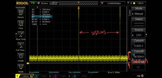
  • This is the current consumption of our nRF52, 100 Ohm put between supply and the IC.
    No matter what interval we set, the peak current always happen at 250ms period. the standby/ sleep current always about 500uA.


    Do you think this is something related to Android Apps -> nRF Toolbox -> UART restrict the interval fix to 250ms?

    If we want to modify from the code of the Apps to longer interval. Can you advise us which file to modify. 

    Thanks!

    Jimmy Ng

  • Hi,

    Sorry for the late response. I have been on holiday for a while.

    1. Did you disable the UART to see if that helps with the 500 uA base current? You can also try to disable the logger module. 
    2. How high are your peak currents? It doesn't have to be the radio. I'm thinking that a 100 Ohm series resistor between your supply and the IC might cause significant voltage drops that are possibly resetting your IC. 
    3. Is the interval exactly 250 ms?
    4. Can you zoom in on the peaks? It might give us a clue about what is causing them. 

    It is the central that ultimately decides on what connection interval to use, but it will always try to use an interval between the min and max value provided by the peripheral. You can try to set both min and max value to 1800 ms if you want to force the central to use that exact interval. 

    Martin

Reply
  • Hi,

    Sorry for the late response. I have been on holiday for a while.

    1. Did you disable the UART to see if that helps with the 500 uA base current? You can also try to disable the logger module. 
    2. How high are your peak currents? It doesn't have to be the radio. I'm thinking that a 100 Ohm series resistor between your supply and the IC might cause significant voltage drops that are possibly resetting your IC. 
    3. Is the interval exactly 250 ms?
    4. Can you zoom in on the peaks? It might give us a clue about what is causing them. 

    It is the central that ultimately decides on what connection interval to use, but it will always try to use an interval between the min and max value provided by the peripheral. You can try to set both min and max value to 1800 ms if you want to force the central to use that exact interval. 

    Martin

Children
No Data
Related