This post is older than 2 years and might not be relevant anymore
More Info: Consider searching for newer posts

Antenna for nRF8001

Hi support team,

I am currently working with the nRF8001 that I wanted to integrated on a my PCB.I would like to know if you have an antenna to recommend to work with the nRF8001 ? We are aiming to transmit data closely, so the max distance will be 10m, and the part has to be the tiniest as possible (for working in pairing and beacon mode).

I know that many topic were already posted about that, but I never found a clear answer.

Thanks for your help,

Florent

Parents
  • Hi Florent,


    As your requirement is for the part to be the tiniest possible, you are pretty much stuck with ceramic chip antennas. In this case you should choose one whose 'recommended mounting' fits with your intended mounting. I.e., if you plan on putting it in a corner of your PCB ('corner mount'), do not pick one that is designed for/recommended for mounting in the end of an elongated PCB ('end mount'). If you plan on having metal objects, e.g. a battery, directly underneath, then you might want to consider an 'on ground antenna' to reduce the negative effects from the metal.


    As with all our nRF5x and nRF24 devices, the nRF8001 operate in the 2.4 GHz ISM band, any single-ended antenna designed for operation between 2400 MHz and 2480 MHz will work.


    Best regards,

    Andreas

Reply
  • Hi Florent,


    As your requirement is for the part to be the tiniest possible, you are pretty much stuck with ceramic chip antennas. In this case you should choose one whose 'recommended mounting' fits with your intended mounting. I.e., if you plan on putting it in a corner of your PCB ('corner mount'), do not pick one that is designed for/recommended for mounting in the end of an elongated PCB ('end mount'). If you plan on having metal objects, e.g. a battery, directly underneath, then you might want to consider an 'on ground antenna' to reduce the negative effects from the metal.


    As with all our nRF5x and nRF24 devices, the nRF8001 operate in the 2.4 GHz ISM band, any single-ended antenna designed for operation between 2400 MHz and 2480 MHz will work.


    Best regards,

    Andreas

Children
  • Hi Andreas,

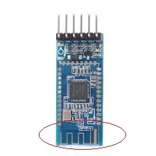
    Is this one a ceramic chip antenna ? 

    What do you call a "in a corner of your PCB" ?  Is there a specific place to put the antenna on a chip (our is going to be a circle) ? I guess the one for mounting in the end of an elongated PCB ('end mount' as you said), it this kind of device am I right ? 

    We plan to havce a supercap and n aluminium standoff as well, so we might consider this option. What is the negative effects from the metal ? 

    Do you have a brand to recommend then ?

    Thanks for your help, much appreciated,

    Florent

  • Hi Florent,


    That is indeed a chip antenna. It might also be known as SMD antenna or surface mount antenna.


    By "in the corner of your PCB" I mean such as this:


    It basically means that the ground plane or ground pour (orange in the image) is shaped around the antenna. Some deviation is possible, as an example this can work just fine in a circular PCB if you make a 'corner indent' in the ground pour, around the antenna, but it should not be positioned as in your 1st image. That one is, as you say, 'end mount'.

    Circular PCBs often work well with 'center mount' antennas (mounted along the far edge of a PCB), as can be see by Johanson antenna selection guide.


    Metal disrupts the electromagnetic field surrounding the antenna, preventing it from resonating and thus transmitting/receiving wireless signals. Antennas such as this are designed for working with ground plane underneath, and therefore are not affected by metal underneath as much. I have mixed experiences about this though so I would avoid it if possible. Other similar antennas:

    https://www.molex.com/molex/products/datasheet.jsp?part=active/0479480001_ANTENNAS.xml

    https://productfinder.pulseeng.com/productSearch/w3001


    We have not noticed any particular difference between manufacturers in terms of performance. It is more important that the recommended mounting is replicated. Differences in pricing, support etc we have no knowledge about unfortunately.


    Best regards,

    Andreas

  • Hi Andreas,

    I had a look on what you gave me, and I have few questions: 

    - On the datasheet, there is always the no ground area (yellow) and the grounded area (orange). So I assume that I can put all the component that I need on the grounded area, but I should let the yellow area free of component am I right ? 

    -On the circular mount part 3, there is not the dimension of the no ground area, and no accurate schematic, should I take the mounting configuration 1 or 2? Or is the mounting consideration 1,2 and 4 are already made for a circular mount () what is the difference betwenn those if so ? ) ?

          Datasheet circular mounted scheme (no dimension) for the 2450AT18D0100 =>

          Datasheet regular mounted scheme (dimension) for the 2450AT18D0100 =>

    - I saw that the 50 Ohm trace can be reduced as well, is there a minimal distance or can we use it as long as it suits our PCB ? 

    Thanks a lot for your help again, really useful,

    Florent

  • Hi,

    Florent Muret said:
    So I assume that I can put all the component that I need on the grounded area, but I should let the yellow area free of component am I right ?

    Correct, the no ground area (yellow) should be free of components, obstructions, traces, objects etc. and sized according to the datasheet. Components and other object should be placed on the ground area (orange), if most of the outer layers are covered by components etc. you should add an internal ground plane and keep it as 'solid' as possible (little/no trace routing).


    As for the circular PCB, either consideration should work fine, but for convenience it might be practical to use consideration 2, which leaves more of the radius for battery, etc underneath.


    As long as the transmission line has 50 ohm impedance it can be pretty much as long as you want. The longer it is though, the longer the transmission line loss will be, so you might not want to overdo it if possible.


    Best regards,

    Andreas

  • Hi Andreas,

    Ok got it !

    So what is the difference between those different mounting consideration ? For the consideration 2, it means that blue area should contains all the battery/metal/LCD component (close to the no ground area) am I right ? 

    Ok fair enough !

    Thanks for your help,

    Florent

Related