This post is older than 2 years and might not be relevant anymore
More Info: Consider searching for newer posts

PPI Configuration to Count Pulses

I have been reading the nRF52840 product specification guide and find the PPI an interesting feature potential to use in my application.  I'm would like if possible to connect an RTC and 2nd timer in count mode to be triggered by the same GPIO input.    I'm new to the nRF52840 and not quite in productive programming it yet.  Need the help from outside resources and example code that helps me.

So...

I want to count fault pulses from a very reliable pulse train (it has very accurate timing from a system MCU).  The fault pulse train has fault patterns ranging from one pulse to ten pulses in each train when a system fault LED lights from a separate MCU in our system.  Want to use the nRF52840 to not only light one of two possible fault icon LED (much like the example of a check engine lite to a car), but I also want to broadcast it out BLE (a later priority to solve in code).

Previous help from the Nordic Zone mentioned the the use of an RTC that times out during the pause in the pulse train two allow the count from a 2nd timer in count mode to be fetched.  The same GPIO used to sense the system LED fault pulses will trigger both timers through the configuration of the PPI.

The image below shows 3 waveforms taken from my white board.   The D2 Fault LED shown is showing a 5 pulse fault code that has meaning in the system for a type of fault.  The fault pulse pattern is active low for 250mS duration pulses with 250mS delay before more fault pulses.  There is a 1.25 second pause before a repeat pattern of the fault code takes place again.  The overall goal is to translate this fault pattern to an accurate count value, determine from count as to what fault icon to light and transmit via BLE the fixture ID number and type of fault translated from the fault.

The 2nd waveform below shows an RTC timer that  triggered by the active low edge of the fault pattern.   The time out for the RTC is 550mS.  Since the repeat active low edges of the fault pulse happens every 500ms, the RTC never times out.  However; when there is no active low during the 1.25sec pause the RTC times out and is the perfect time to get the count from the timer in count mode.

The last waveform shown is the timer in count mode that is triggered by the same active low falling edge fault pulse signal that triggers the RTC.   This timer once triggered "I assume" can time out in 100mS and keep a count of one on every trigger input from the fault pulse GPIO input.  The count will be fetched when the RTC times out only during the time it sees no active low falling edge from the fault pulse input during the 1.25sec pause.

See the image below for a better visual of what I want to do.    Need help on code that I can take further.   I have viewed example code similar to what I need to achieve and found nothing.


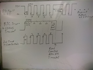
Thanks for your help,

Allen

Parents
  • Hi,

    I have attached two examples that should be usefull for implementing the behavior you want.

    The first example, pin_rise_count_ppi_gpiote_timers.zip, shows how to count the number of falling flanks on a GPIO. One timer is used in count mode, while another timer is used in timer mode to capture and print the number counted by the first timer every 10 ms.

    The second example, second_count_ppi_rtc_timers.zip, use a timer in count mode to count number of seconds. This example use a RTC to trigger the count task of the timer every 1 second.

    It should not be too big of a task to combine the functionality of these two examples into your own desired behavior.

    You should setup a GPIOTE interrupt on high to low change on the GPIO, and connect this to three TASKS (note that this might require multiple PPI channels): RTC->TASKS_START + RTC->TASKS_CLEAR + TIMER_TASKS_COUNT. Then you need to connect the event when the RTC times out (RTC->EVENTS_COMPARE[x]), to the capture task of the timer (TIMER->TASKS_CAPTURE[x]). This will store the count value in TIMER->CC[x] register. If you setup the RTC to trigger an interrupt on the timeout, you can read back this captured count value from the timer and handle this further. Remember to clear the timer at this point, making it ready for next count task.

    Hope this helps wit implementing your feature!

    Best regards,
    Jørgen

Reply
  • Hi,

    I have attached two examples that should be usefull for implementing the behavior you want.

    The first example, pin_rise_count_ppi_gpiote_timers.zip, shows how to count the number of falling flanks on a GPIO. One timer is used in count mode, while another timer is used in timer mode to capture and print the number counted by the first timer every 10 ms.

    The second example, second_count_ppi_rtc_timers.zip, use a timer in count mode to count number of seconds. This example use a RTC to trigger the count task of the timer every 1 second.

    It should not be too big of a task to combine the functionality of these two examples into your own desired behavior.

    You should setup a GPIOTE interrupt on high to low change on the GPIO, and connect this to three TASKS (note that this might require multiple PPI channels): RTC->TASKS_START + RTC->TASKS_CLEAR + TIMER_TASKS_COUNT. Then you need to connect the event when the RTC times out (RTC->EVENTS_COMPARE[x]), to the capture task of the timer (TIMER->TASKS_CAPTURE[x]). This will store the count value in TIMER->CC[x] register. If you setup the RTC to trigger an interrupt on the timeout, you can read back this captured count value from the timer and handle this further. Remember to clear the timer at this point, making it ready for next count task.

    Hope this helps wit implementing your feature!

    Best regards,
    Jørgen

Children
  • Hi Jorgen

    Thanks for this example.

    This is pretty much what I need in my application but also to integrate with the softdevice. I copied the code into my project but the compiler is unhappy as follows. Can you give me some clues on this error please? 

    BR Martin

    Building ‘ble_app_blinky_pca10040_s132’ from solution ‘ble_app_blinky_pca10040_s132’ in configuration ‘Release’
      Compiling ‘main.c’
        nrfx.h
        nrf_gpio.h
        boards.h
        main.c
        'NRFX_TIMER1_INST_IDX' undeclared here (not in a function); did you mean 'NRFX_TIMER_INSTANCE'?
        in definition of macro 'NRFX_CONCAT_3_'
        in expansion of macro 'NRFX_CONCAT_3'
        in expansion of macro 'NRFX_TIMER_INSTANCE'
        in expansion of macro 'NRF_DRV_TIMER_INSTANCE'
        'NRFX_TIMER2_INST_IDX' undeclared here (not in a function); did you mean 'NRFX_TIMER_INSTANCE'?
        in definition of macro 'NRFX_CONCAT_3_'
        in expansion of macro 'NRFX_CONCAT_3'
        in expansion of macro 'NRFX_TIMER_INSTANCE'
        in expansion of macro 'NRF_DRV_TIMER_INSTANCE'
        initialization of 'void (*)(uint8_t,  uint8_t)' {aka 'void (*)(unsigned char,  unsigned char)'} from incompatible pointer type 'void (*)(uint8_t,  uint8_t,  compound_type_t)' {aka 'void (*)(unsigned char,  unsigned char,  struct <anonymous>)'} [-Wincompatible-pointer-types]
        (near initialization for 'buttons[0].button_handler')
        initialization of 'void (*)(uint8_t,  uint8_t)' {aka 'void (*)(unsigned char,  unsigned char)'} from incompatible pointer type 'void (*)(uint8_t,  uint8_t,  compound_type_t)' {aka 'void (*)(unsigned char,  unsigned char,  struct <anonymous>)'} [-Wincompatible-pointer-types]
        (near initialization for 'buttons[1].button_handler')
        initialization of 'void (*)(uint8_t,  uint8_t)' {aka 'void (*)(unsigned char,  unsigned char)'} from incompatible pointer type 'void (*)(uint8_t,  uint8_t,  compound_type_t)' {aka 'void (*)(unsigned char,  unsigned char,  struct <anonymous>)'} [-Wincompatible-pointer-types]
        (near initialization for 'buttons[2].button_handler')
        initialization of 'void (*)(uint8_t,  uint8_t)' {aka 'void (*)(unsigned char,  unsigned char)'} from incompatible pointer type 'void (*)(uint8_t,  uint8_t,  compound_type_t)' {aka 'void (*)(unsigned char,  unsigned char,  struct <anonymous>)'} [-Wincompatible-pointer-types]
        (near initialization for 'buttons[3].button_handler')
    Build failed

  • Looks like you ar missing some config in your sdk_config.h file (possibly TIMER1_ENABLED). How did you integrate it into the softdevice project? Which SDK version are you using?

  • In the first example, why does in_pin_handler do nothing? does the code work as it is? and could you clarify whether it is counting the number OF falling flanks or the timer number AT falling flanks? It seems nrf_drv_timer_capture_get returns captured value, which looks like it is returning the timer number AT falling flanks.

  • Hi, in_pin_handler() does nothing because there is no interrupts enabled for the input pin (second parameter to nrf_drv_gpiote_in_event_enable() set to false), so the handler will never be called. The code works as it is, by using HW resources like GPIOTE, PPI and TIMERs.

    When the input pin state changes from low to high, the GPIOTE peripheral will trigger an event, which will be sent over a PPI channel to trigger the COUNT task in one timer. A second timer is setup to read the count value of the first timer at a regular interval (defined by COUNT_READ_INTERVAL). 

    To sum up, the second timer will read the number OF rising flanks on the input pin in the past interval.

  • Can I ask a question about timer handler?

    i see when timer handler is used, nrf_drv_timer_extended_compare is getting used on pretty much every single example.

    But I don't think I need this function for my project. does the timer handler run without this function?

    What triggers timer handler?

    does it run constantly without trigger? if so that's what I need at the moment.

Related