This post is older than 2 years and might not be relevant anymore
More Info: Consider searching for newer posts

nrfjprog can't read/write/erase correctly nrf52840 MX25R6435F QSPI

Greetings!

Using the NRF52840 PDK, I succesfully erase, write and read without any modifications!

I have custom boards which involved a NRF52840 and a MX25R6435F (so same setup as the PDK), I just made modifications on the QspiDefault.ini since my pinout is different.

I try to erase all the flash chip or just one page but nrfjprog doesn't returned me any errors (so success ?) but it has no effects since I can read the chip which gives me 999999999999....9

I also try the --qspicustominit, different write and read mode but no changes.

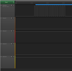
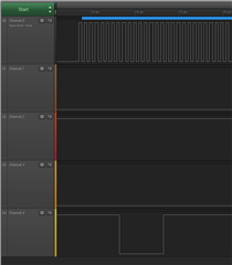
(Assuming the wires are correctly solde ); channel 0 is clock, channel 1 is DIO0, channel 2 is DIO1 ...

This is the result for running a read of 8 bytes:

Thanks for your time.

Parents
  • Hi,

    Are you able to program the board using nrfjprog?

    Could you provide the log file from nrfjprog (add the parameter --log and provide file log.log)? Please also upload scematics for your board.

    Best regards,
    Jørgen

  • of course; like I said previously it's the default one with just some pin changing to match my design

    ; nrfjprog.exe configuration file.
    
    [DEFAULT_CONFIGURATION]
    ; Define the capacity of the flash memory device in bytes. Set to 0 if no external memory device is present in your board.
    MemSize = 0x800000
    
    ; Define the desired ReadMode. Valid options are FASTREAD, READ2O, READ2IO, READ4O and READ4IO
    ReadMode = READ4IO
    
    ; Define the desired WriteMode. Valid options are PP, PP2O, PP4O and PP4IO
    WriteMode = PP4IO
    
    ; Define the desired AddressMode. Valid options are BIT24 and BIT32
    AddressMode = BIT24
    
    ; Define the desired Frequency. Valid options are M2, M4, M8, M16 and M32
    Frequency = M8
    
    ; Define the desired SPI mode. Valid options are MODE0 and MODE3
    SpiMode = MODE0
    
    ; Define the desired SckDelay. Valid options are in the range 0 to 255
    SckDelay = 0x80
    
    ; Define the desired IO level for DIO2 and DIO3 during a custom instruction. Valid options are LEVEL_HIGH and LEVEL_LOW
    CustomInstructionIO2Level = LEVEL_LOW
    CustomInstructionIO3Level = LEVEL_HIGH
    
    ; Define the assigned pins for the QSPI peripheral. Valid options are those existing in your device
    CSNPin = 24
    CSNPort = 0
    SCKPin = 19
    SCKPort = 0
    DIO0Pin = 21
    DIO0Port = 0
    DIO1Pin = 23
    DIO1Port = 0
    DIO2Pin = 22
    DIO2Port = 0
    DIO3Pin = 17
    DIO3Port = 0
    
    ; Define the Index of the Write In Progress (WIP) bit in the status register. Valid options are in the range of 0 to 7.
    WIPIndex = 0
    
    ; Define page size for commands. Valid sizes are PAGE256 and PAGE512.
    PPSize = PAGE256
    
    ; Custom instructions to send to the external memory after initialization. Only used if --qspicustominit option is given in the call to nrfjprog. Format is
    ; instruction code plus data to send in between optional brakets. Numbers can be given in decimal, hex (starting with either 0x or 0X) and binary (starting
    ; with either 0b or 0B) formats. The custom instructions will be executed in the order found.
    ; This example includes two commands, first a WREN (WRite ENable) and then a WRSR (WRite Satus Register) enabling the Quad Operation and the High Performance
    ; mode for the MX25R6435F memory present in the nRF52840 DK.
    InitializationCustomInstruction =  0x06
    InitializationCustomInstruction =  0x01, [0x40, 0, 0x2]

Reply
  • of course; like I said previously it's the default one with just some pin changing to match my design

    ; nrfjprog.exe configuration file.
    
    [DEFAULT_CONFIGURATION]
    ; Define the capacity of the flash memory device in bytes. Set to 0 if no external memory device is present in your board.
    MemSize = 0x800000
    
    ; Define the desired ReadMode. Valid options are FASTREAD, READ2O, READ2IO, READ4O and READ4IO
    ReadMode = READ4IO
    
    ; Define the desired WriteMode. Valid options are PP, PP2O, PP4O and PP4IO
    WriteMode = PP4IO
    
    ; Define the desired AddressMode. Valid options are BIT24 and BIT32
    AddressMode = BIT24
    
    ; Define the desired Frequency. Valid options are M2, M4, M8, M16 and M32
    Frequency = M8
    
    ; Define the desired SPI mode. Valid options are MODE0 and MODE3
    SpiMode = MODE0
    
    ; Define the desired SckDelay. Valid options are in the range 0 to 255
    SckDelay = 0x80
    
    ; Define the desired IO level for DIO2 and DIO3 during a custom instruction. Valid options are LEVEL_HIGH and LEVEL_LOW
    CustomInstructionIO2Level = LEVEL_LOW
    CustomInstructionIO3Level = LEVEL_HIGH
    
    ; Define the assigned pins for the QSPI peripheral. Valid options are those existing in your device
    CSNPin = 24
    CSNPort = 0
    SCKPin = 19
    SCKPort = 0
    DIO0Pin = 21
    DIO0Port = 0
    DIO1Pin = 23
    DIO1Port = 0
    DIO2Pin = 22
    DIO2Port = 0
    DIO3Pin = 17
    DIO3Port = 0
    
    ; Define the Index of the Write In Progress (WIP) bit in the status register. Valid options are in the range of 0 to 7.
    WIPIndex = 0
    
    ; Define page size for commands. Valid sizes are PAGE256 and PAGE512.
    PPSize = PAGE256
    
    ; Custom instructions to send to the external memory after initialization. Only used if --qspicustominit option is given in the call to nrfjprog. Format is
    ; instruction code plus data to send in between optional brakets. Numbers can be given in decimal, hex (starting with either 0x or 0X) and binary (starting
    ; with either 0b or 0B) formats. The custom instructions will be executed in the order found.
    ; This example includes two commands, first a WREN (WRite ENable) and then a WRSR (WRite Satus Register) enabling the Quad Operation and the High Performance
    ; mode for the MX25R6435F memory present in the nRF52840 DK.
    InitializationCustomInstruction =  0x06
    InitializationCustomInstruction =  0x01, [0x40, 0, 0x2]

Children
No Data
Related