This post is older than 2 years and might not be relevant anymore
More Info: Consider searching for newer posts

ST7735 interfacing instructions

After going through the SDK i came across the ST7735 LCD screen example.

On the SDK Page it says example uses the ILI9341 controller, But we can also configure it to use the ST7735 controller. After looking into sdk_config.h it is already enabled as:

// <e> ST7735_ENABLED - st7735 - ST7735R TFT controller
//==========================================================
#ifndef ST7735_ENABLED
#define ST7735_ENABLED 1
#endif

Do i need configure it some where else other than this?

Also wiring is not very clear, can some one point me how wire it with nRF52-DK with ST7735.
link

Parents
  • Hello,

    I am not familiar with this device, but you have to change the SPI driver to match the ST7735.


    In main.c on line 82:

    static const nrf_lcd_t * p_lcd = &nrf_lcd_ili9341;

    change this to:

    static const nrf_lcd_t * p_lcd = &nrf_lcd_st7735;

    And the p_lcd pointer should use the ST LCD screen instead of the ili9341 LCD.


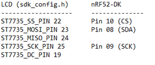
    I am not sure about the wiring. It seems like the defines from the sdk_config seems right, where did you find the numbers in the picture to the right?

    Pin 10 (CS)
    Pin 08 (SDA
    Pin 09 (SCK)

    ?

    I would give this a go:

    NRF:                             ST_LCD (not the ones marked "SD", but the others) :

    22.................................CS

    23.................................SDA

    24................................. --

    25.................................SCK

    19 (DC)........................??


    I am not sure whether the DC is needed. See this thread, where DC is explained. I am not sure, but I suspect that the DC is supposed to be connected to AO. (see this thread)


    Best regards,

    Edvin

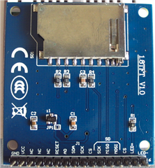
  • Hi Ediv, i tried to match the pins from sdk_config.h with LCD board. So not sure if they are right but will try it today.

    But to which pin should i connect the MISO pin 24 of nRF52-DK to lcd?

  • nRF52-DK SainSmart
    25 SCL
    23 SDA
    22 CS
    19 RS/DC
    ?? RES
    5V VCC
    Gnd GND

    Does this look right Edvin. Pin 24 i am not sure about where to connect. Also should i connect the reset pin on LCD to the reset button is on nRF52-DK?

  • I don't think pin 24 is used on that LCD screen. It looks like the screen doesn't send any data to the nRF.

    MOSI (Master Out Slave In) is the SDA pin, but it doesn't look like the slave has any data out line, so you don't need to connect 24 to anything.

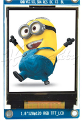
    Where did you find the RES pin on the LCD device?


    I also see that there are two CS pins on the LCD. I don't know which one is for the screen and which one is for the SD card. try both, but I would assume that the one to the left in your picture is for the LCD.

    I am not sure how to connect the RESET pin either. It depends on how it is configured. If the screen resets when the RESET pin is pulled down, then you should connect it to VDD. If it is reset when the RESET pin is pulled up, it should be connected to a pin configured to this (not part of the SPI). It doesn't seem like the example project uses this, so try to set it to VDD. If that doesn't work, you can try to ground it.


    BR,

    Edvin


    If anyone else on this forum has any experience with this LCD screen, please share if you know anything about the pin setup.

  • Thank you very much for your kind help Edvin. It has worked final pins are:

    nRF52-DK SainSmart
    25 SCL
    23 SDA
    22 CS
    19 RS/DC
    vdd RES
    5V VCC
    Gnd GND

    Pin 24 not needed.

    I used this LCD

  • It is not working anymore. It was working last night now when i switched on the board white screen appears. I initially thought that LCD is broken so tested it on arduino with adafruit library that worked screen started working after i pressed reset button on arduino nano. 

    Then i plugged back lcd for nRF52-DK hoping it will work but it did not work. I pressed reset button even reprogrammed firmware few times but it does not work anymore. It prints the log message on putty but LCD does not work with nRF52-DK now.

    Where as when i plug it on arduino LCD works fine after pressing reset button. Not sure what has gone wrong with it now.

    (Also i have found when i just connect scl and sda to LCD from arduino it turns on the white screen. But this does not happen on nRF52-DK.)

  • Hello,

    Not sure, but it might be that it can't deliver enough power if you are using a USB hub. Can you try to connect the USB cable that your DK is connected to directly into the computer?

    BR,

    Edvin

Reply Children
  • Hi Edwin, i have checked vcc power is sufficient. Also it is not connected to hub but directly on machine. I am really puzzled what is wrong it was working one day next day it stopped working without any change.

    Are we sure RESET pin needs to be connected to VDD? 

    I have purchased few other LCD none of them works now. Do i need to power up the scl, sda, dc, cs pin to 5 v like arduino?

    What LCD was used in the GFX example at nordic? I can buy and try that.

  • You don't have a logic analyzer, like the saleae logic analyzer, by chance? It would be interresting to see if there are any difference between SDA (MOSI) on the Arduino and the nRF. 


    regarding the RESET, I am not sure how it behaves. You have to check the datasheet of your screen whether it needs to be grounded or connected to VDD. I believe VDD is typical for these kind of pins. That means that when the pin gets a GND pulse, it will reset.


    As you can see here, it uses the ILI9341.


    Are you sure that there were no changes between the time that it was working and now? Can you try to unzip the SDK again and try with an unmodified version of the example? (only with the changes described to change to the ST LCD screen).


    BR,

    Edvin

  • Thanks for advice I have purchased it now, will receive it soon. Will test it and send the difference here.

Related