This post is older than 2 years and might not be relevant anymore
More Info: Consider searching for newer posts

Help with nRF24L01+ datasheet

Using this sheet

https://www.sparkfun.com/datashe...


I'm trying to figure out two things.


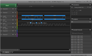
1) There is a section on timing but I'm a bit confused what SPI Clock rate to use (SPI2x, SPR1, SPr0 respectively).  I don't see a way to set the nRF24 via pins (as there clearly are none for clock rate) so I'm left to assume the clock rate is fixed.


2) When setting map tables, what is the packet format of the SPI data?

I see the Register map table and  that you set them with SPI. But how is unclear. I would have expected to see something like.  [command, addressHI, adressLO, byte1, byte2, byte3, etc....]. The ShockBurst appears to have packet data but does not seem to be what I'm looking for.
 

I'm sure its all there just need help.

Parents
  • I was able to find the map table commands on 48, and  I think the clock is very loose but a max of 10mhz?

    so on my ARM chip I did this (bits should be obvious).

    // Configure the SPI to Master, 8-bit mode @10000 kBits/sec
        SPIdrv->Control(ARM_SPI_MODE_MASTER | ARM_SPI_MSB_LSB | ARM_SPI_SS_MASTER_SW | ARM_SPI_DATA_BITS(8), 10000000);


        SPIdrv->Control(ARM_SPI_CONTROL_SS, ARM_SPI_SS_INACTIVE); // SS line = INACTIVE = HIGH

    //set up rf channel

    testdata_out[8] = { 0x25, 1  };//cmd 5th bit on to write (address 0x05)  , data channel 1.

     SPIdrv->Send(testdata_out, sizeof(testdata_out));

    Did I get that about right? Worried about my m/l significant bits.

  • Hi,

    Seems you have this already sorted out.

    0x25 means write to address 5 with the value 1. I can also see that STATUS register is 0x0E, because that is always clocked out on first byte.

    Best regards,
    Kenneth

  • Been away from the project for a bit but I'm back now. I wanted to see if anyone could glance at my code and see what I'm doing wrong here.

    I'm trying to send data to a radio listening on channel 5, pipe 0. but I'm not seeing data.

    does CSN normally work with SS of the SPI?  OR does it need to go high at a manually controlled time. I just connected it to the active/inactive SS pin of the SPI. I also see talk about pulsing the line for 1ms, is this needed?

    This is my code from the sender. The comments should show my intentions. Though nothing is showing up on the receiving end.

    also the rf setup does not make any sense to me. Most people are setting it to 0x06 for 1MB but that looks like reserved to me and when set to 1MB in the Arduino code its a 0x01 that looks like 2MB? And what exactly does this mean? This bit is don’t care if RF_DR_LOW is set

    On my transmit end I use an arm. The SPI checks out (I see it on my analyzer)
    I manualy hold CE hi and I get 0x1e for each byte. 
    	
    	spi_send(2,0x20,0x0a,0x00,0x00,0x00,0x00,0x00,0x00);//transmit //5a
    	//spi_send(2,0x24,0x00,0x00,0x00,0x00,0x00,0x00,0x00);//auto transmit off
    	spi_send(2,0x25,0x05,0x00,0x00,0x00,0x00,0x00,0x00); // chanel 5
    	spi_send(2,0x26,0x26,0x00,0x00,0x00,0x00,0x00,0x00);//data rate of 1mb 06 is somehow 1mb. 26 shoudl be 250k
    	spi_send(2,0x23,0x03,0x00,0x00,0x00,0x00,0x00,0x00);//addres for 5 bytes
    
        const char *addr = "Seat1";
    	spi_send(6,0x30,addr[0],addr[1],addr[2],addr[3],addr[4],0x00,0x00);//pipe 0
    	
    	 spi_send(2,0x31,0x07,0x00,0x00,0x00,0x00,0x00,0x00);//7 bytes for data.
    	spi_send(2,0x21,0x00,0x00,0x00,0x00,0x00,0x00,0x00);//auto ack (3f to enable : 00 to not )
    
        while(1)
    	{			
    		spi_send(8,0xa0,0x01,0x02,0x03,0x04,0x05,0x06,0x07);
    
    		//1ms pulse
    		SPIdrv->Control(ARM_SPI_CONTROL_SS, ARM_SPI_SS_ACTIVE); // SS line = ACTIVE = LOW
    		for (int f=1;f<4450;f++)  { for (double g=0;g>0;g++)  {}; }
    		SPIdrv->Control(ARM_SPI_CONTROL_SS, ARM_SPI_SS_INACTIVE); // SS line = INACTIVE = HIGH
    			
    		osDelay(1000);
    	}
    }
    
    		
    The recive end is an arduino. I never really used this thing before but its a built in library. 
    
    
    RF24 radio(7, 8); // CE, CSN
    void setup() {
      radio.begin();
      radio.setChannel(5);
      const byte add[5] = {'S','e'.'a','t','1' };
      radio.openReadingPipe(0, add);
      radio.setPALevel(RF24_PA_MIN);
    }
    void loop() {
      Serial.begin(115200);
      delay(5);
      radio.startListening();
      if ( radio.available()) 
      {
        Serial.println("waiting");
        while (radio.available())
        {
          char i[7];
          radio.read(&i, sizeof(i));
          Serial.println(i);
        }
     
      }
    }


  • is this needed?

    //Pulse CE to start transmission
        SPI_CE = HIGH;
        __delay_ms(1);
        SPI_CE = LOW;
  • That is required, since the packet is triggered to be sent in TX. In RX is should be high all the time while receiving.

  • That works, got most everything set up but the receiver. Receiver is now on ARM and my receive codes is something like

    spi_send(2,0x61,0x00,0x00,0x00,0x00,0x00,0x00,0x00); //get state
    spi_send(1,0xe2,0x00,0x00,0x00,0x00,0x00,0x00,0x00); //flush

    I always get 0x0e empty fifo but I also get the data i'm looking for. I want to basically get the data and dump the buffer so I always have fresh data. I'm not able to make that work.

    I'm thinking maybe I need to use 27 or 37 hex and set the flags but i'm not sure.

Reply
  • That works, got most everything set up but the receiver. Receiver is now on ARM and my receive codes is something like

    spi_send(2,0x61,0x00,0x00,0x00,0x00,0x00,0x00,0x00); //get state
    spi_send(1,0xe2,0x00,0x00,0x00,0x00,0x00,0x00,0x00); //flush

    I always get 0x0e empty fifo but I also get the data i'm looking for. I want to basically get the data and dump the buffer so I always have fresh data. I'm not able to make that work.

    I'm thinking maybe I need to use 27 or 37 hex and set the flags but i'm not sure.

Children
Related